The Complete Guide to Hardware Pipeline Design with Backpressure
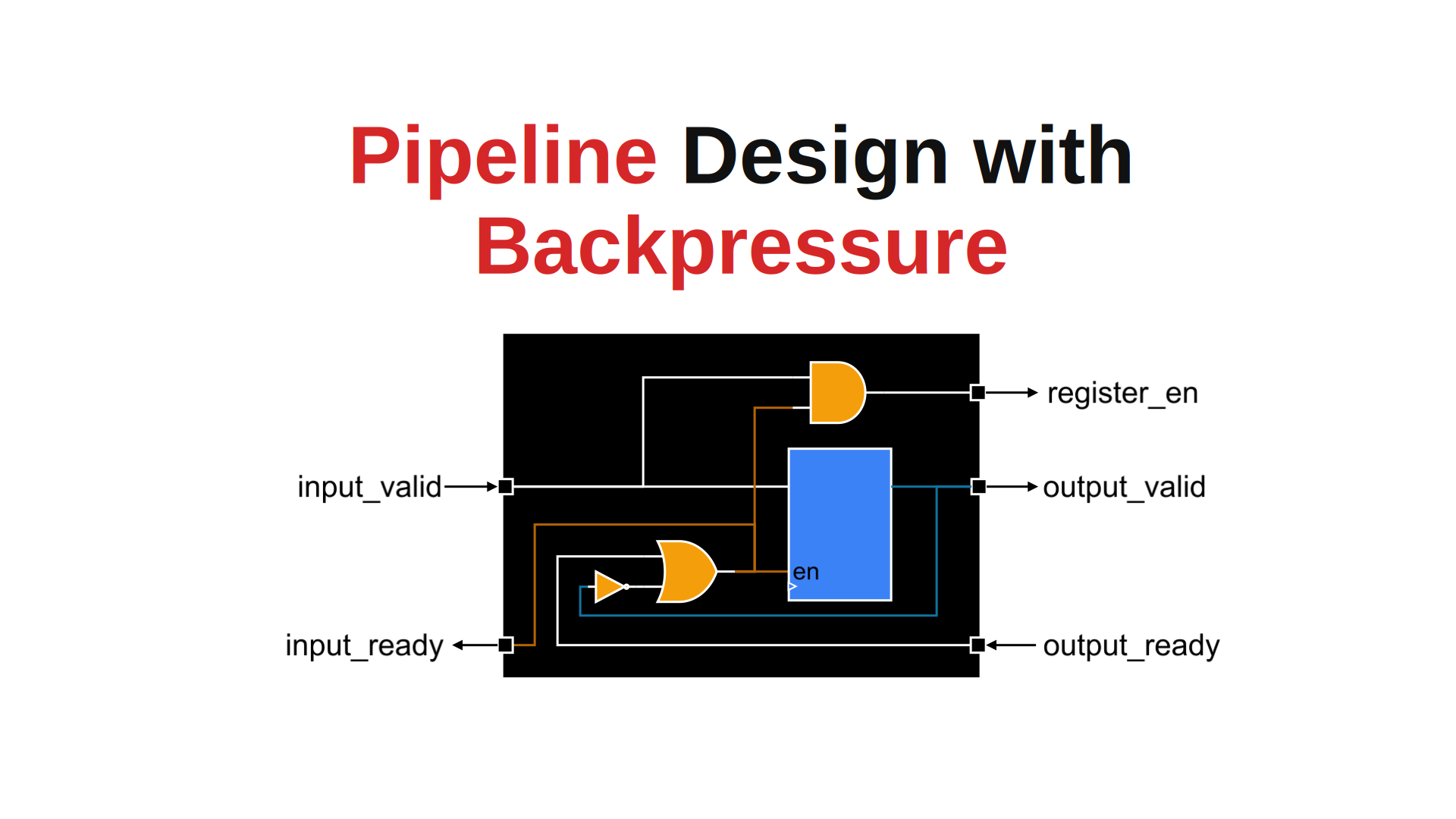
Pipelining is the first tool most hardware engineers reach for when a design cannot meet its timing target. Splitting a long computation into stages is the easy part; the hard part is what happens when the consumer downstream stops accepting data. If your pipeline cannot stall safely, it will either drop results or corrupt them.
This post walks through a pipeline structure built on a ready/valid handshake, in which the ready signal propagates backward through the stages so the whole pipeline stalls and resumes automatically, without a central controller.
Table of Contents
- Table of Contents
- Pipeline vs. No Pipeline for Computation
- Why Pipelining Helps Computation
- A Practical Problem: Memory Contention in an Accelerator
- Pipeline Structure and Control Signals
- Handshake Rules
- A Reusable Pipeline Stage
- Issue: The Long Combinational Ready Path
- Conclusion
- References
Pipeline vs. No Pipeline for Computation
A pipeline is one of the simplest ways to make a computation engine faster. The basic idea is to split a long piece of work into smaller stages, insert registers between them, and let several inputs move through the machine at the same time.
This matters because most algorithms are limited by how much work must fit into one clock cycle. Without pipelining, a long chain of arithmetic and logic becomes a long critical path. With pipelining, the same work is distributed across stages, so the design can usually run at a higher clock frequency and sustain higher throughput, at the cost of increased latency.
For example, consider a multiply-accumulate block, a FIR filter, a matrix inner product, or a floating-point arithmetic unit. In all of those cases, the question is the same:
- Should I do everything in one cycle and keep the design simple?
- Or should I split the algorithm into stages and get better throughput?
The tradeoff is straightforward:
- No pipeline: lower design complexity, but one long combinational path and a lower maximum clock frequency.
- Multi-stage pipeline: more registers and more control logic, but a shorter critical path and higher throughput.
The key point is that pipelining improves throughput, not latency. A single item still takes several cycles to pass through the machine, but once the pipeline is full, you can accept one new item every cycle.
Why Pipelining Helps Computation
Consider a simple compute kernel:
\[y = (a \times b) + (c \times d) + e\]No pipeline
In a single-stage design, all of this happens in one cycle:
- multiply
a * b - multiply
c * d - add the products
- add
e - optionally normalize, round, clamp, or format the result
The clock period must therefore be long enough for every one of those operations to complete. If the path is too long, the design fails timing (setup violations and negative setup slack) or needs a much slower clock.
With a pipeline
Now split the work into stages:
- Stage 1: capture the inputs
- Stage 2: perform the multiplications and alignment
- Stage 3: finish the addition, rounding, and output formatting
Each stage does less work, so the clock period can be shorter. The total latency increases by a few cycles, but the machine can process new inputs continuously once the pipeline is full.
That is the real reason pipelines exist in hardware compute engines.
A Practical Problem: Memory Contention in an Accelerator
Consider another practical example.
An accelerator continuously reads data from Memory A, performs a computation that takes several clock cycles, and writes the result into Memory B.
While the accelerator is reading from Memory A, CPU A also accesses Memory A. Since CPU A has higher priority, the accelerator must wait.
Similarly, when the accelerator tries to write into Memory B, CPU B requests data from Memory B. Because CPU B also has higher priority, the accelerator cannot write; it must stall its computation and stop reading new data from Memory A.

Note that the stall does not stay local. If the write side blocks, the compute stages must freeze, and the read side must stop issuing new requests, otherwise the data already in flight is lost. This is what backpressure means: a stall at the output has to travel backward, stage by stage, all the way to the source.
Goal: design an accelerator in which backpressure propagates backward automatically.
Pipeline Structure and Control Signals
Each pipeline stage has four control signals:
- input_valid: the upstream producer is presenting valid data at this stage’s input.
- input_ready: this stage can accept new data in the current cycle.
- output_valid: this stage is holding valid data for the downstream consumer.
- output_ready: the downstream consumer can accept data in the current cycle.
Data moves from one stage to the next on a clock edge where valid and ready are both high. That single rule is the whole protocol; it is the same handshake used by AXI-Stream and by most latency-insensitive designs.

Deriving input_ready
A stage can accept new data in two situations:
- The stage is empty, that is, it holds no valid data to pass on (output_valid is low). Nothing can be overwritten, so new data is welcome.
- The stage is full, but the downstream stage is taking the data this cycle (output_ready is high). The register is freed on the same clock edge that loads the new value.
Combining the two cases, input_ready is high when the stage is empty or the downstream stage is ready:
input_ready = !output_valid || output_ready
Or, as gates:

This is what makes the structure bubble-free: because a full stage still accepts data while it is being drained, the pipeline sustains one transfer per cycle instead of alternating between load and drain cycles.
Deriving register_en and output_valid
When input_valid and input_ready are both high, a transfer takes place: the stage captures the new data and starts processing it. So the pipeline register is enabled (register_en is high), and on the next clock cycle output_valid goes high to indicate that the stage now holds valid data.
Note that the two registers are enabled by different conditions. The valid bit updates whenever the stage is ready, so a bubble (an invalid cycle) can shift in and empty the stage. The data registers only update on an actual transfer, which also saves switching power while bubbles move through the pipeline.

The Complete Pipeline
The complete pipeline is shown below. The valid signal propagates forward, and the ready signal propagates backward. A stage accepts new data if the next stage can accept it, or if the stage is currently empty. This structure handles backpressure automatically and keeps the data flowing without any central stall controller.

Using this structure, we can build a three-stage pipeline for the compute kernel above: the first stage captures the inputs, the second performs the multiplications, and the third completes the additions and produces the final result. When the final output_ready is low while output_valid is high, the last stage deasserts its input_ready, so it stops accepting new data. That ready signal then propagates backward through the pipeline, stalling each stage in turn until the downstream consumer accepts data again.

Handshake Rules
A few rules keep this protocol safe, and breaking any of them is the usual cause of a deadlocked or lossy pipeline:
- Never make valid depend combinationally on ready. A stage must assert output_valid based only on its own state. If valid waits for ready while ready waits for valid, the two sides deadlock, or synthesis reports a combinational loop.
- Once valid is asserted, hold it, and hold the data with it, until the transfer completes. The consumer may take several cycles to assert ready, and the payload must not change in the meantime.
- Ready may be deasserted freely. It is allowed to depend combinationally on the downstream ready, which is exactly what the equation above does.
- Reset the valid bits, not necessarily the data. Only the valid chain needs a reset value; the datapath registers can start up undefined because no consumer will look at them until a valid marker arrives.
A Reusable Pipeline Stage
The whole structure fits into one small, synthesizable module. Instantiate it once per stage and put the stage’s combinational logic into the datapath register.
SystemVerilog
module pipeline_stage #(
    parameter int WIDTH = 32
) (
    input  logic             clk_i,
    input  logic             reset_n_i,

    // Upstream handshake
    input  logic             input_valid_i,
    output logic             input_ready_o,
    input  logic [WIDTH-1:0] data_i,

    // Downstream handshake
    output logic             output_valid_o,
    input  logic             output_ready_i,
    output logic [WIDTH-1:0] data_o
);

    logic register_en;

    // The stage accepts new data when it is empty, or when the downstream
    // stage is taking the data it currently holds.
    assign input_ready_o = ~output_valid_o | output_ready_i;

    // A transfer happens only when both sides agree.
    assign register_en = input_valid_i & input_ready_o;

    // Valid flow: shifts whenever the stage is ready, so bubbles can drain out.
    always_ff @(posedge clk_i or negedge reset_n_i) begin
        if (!reset_n_i)         output_valid_o <= 1'b0;
        else if (input_ready_o) output_valid_o <= input_valid_i;
    end

    // Datapath: updates only on an actual transfer.
    always_ff @(posedge clk_i or negedge reset_n_i) begin
        if (!reset_n_i)       data_o <= '0;
        else if (register_en) data_o <= data_i;  // replace with this stage's function
    end

endmodule
VHDL
library ieee;
use ieee.std_logic_1164.all;

entity pipeline_stage is
    generic (
        WIDTH : positive := 32
    );
    port (
        clk_i          : in  std_logic;
        reset_n_i      : in  std_logic;

        -- Upstream handshake
        input_valid_i  : in  std_logic;
        input_ready_o  : out std_logic;
        data_i         : in  std_logic_vector(WIDTH-1 downto 0);

        -- Downstream handshake
        output_valid_o : out std_logic;
        output_ready_i : in  std_logic;
        data_o         : out std_logic_vector(WIDTH-1 downto 0)
    );
end entity pipeline_stage;

architecture rtl of pipeline_stage is

    -- Internal copy of the output valid bit, because input_ready reads it back
    signal output_valid_q : std_logic;
    signal input_ready    : std_logic;
    signal register_en    : std_logic;

begin

    -- The stage accepts new data when it is empty, or when the downstream
    -- stage is taking the data it currently holds.
    input_ready <= (not output_valid_q) or output_ready_i;

    -- A transfer happens only when both sides agree.
    register_en <= input_valid_i and input_ready;

    input_ready_o  <= input_ready;
    output_valid_o <= output_valid_q;

    -- Valid flow: shifts whenever the stage is ready, so bubbles can drain out.
    process (clk_i, reset_n_i)
    begin
        if reset_n_i = '0' then
            output_valid_q <= '0';
        elsif rising_edge(clk_i) then
            if input_ready = '1' then
                output_valid_q <= input_valid_i;
            end if;
        end if;
    end process;

    -- Datapath: updates only on an actual transfer.
    process (clk_i, reset_n_i)
    begin
        if reset_n_i = '0' then
            data_o <= (others => '0');
        elsif rising_edge(clk_i) then
            if register_en = '1' then
                data_o <= data_i;  -- replace with this stage's function
            end if;
        end if;
    end process;

end architecture rtl;
Both versions describe exactly the same hardware: two enabled registers and two gates.
Chaining the Stages
Chaining stages is then just a matter of wiring the handshakes together: the output_valid of one stage drives the input_valid of the next, and the input_ready of the next stage drives the output_ready of the previous one.
Issue: The Long Combinational Ready Path
In this design, input_ready is combinational, and it depends on the downstream output_ready. Chain enough stages together and the ready signal has to travel through every stage in a single clock cycle, from the consumer at the end back to the producer at the front. In a deep pipeline this backward path easily becomes the critical path and cancels the frequency gain you pipelined for in the first place.
The fix is to break the chain every few stages (typically four to eight, depending on the technology and the target frequency) by registering the ready signal. Registering ready cannot be done on its own, though: while the registered stall is still travelling backward, the upstream stage may already have launched another transfer, and that data has nowhere to go. The stage that registers ready therefore needs one extra buffer entry to absorb the in-flight item. This is what a skid buffer (also called a register slice, and what AXI implementations use for exactly this reason) does: two storage slots plus the logic to deassert ready one cycle early.
For larger distances, a small FIFO between pipeline clusters serves the same purpose while also decoupling the two sides in throughput, and credit-based flow control replaces the backward ready path entirely with a counter at the producer.
Conclusion
Pipelining restructures a computation so that expensive work is divided into smaller stages, buying throughput and a shorter critical path at the cost of latency and extra control logic.
The ready/valid structure shown here adds one property that matters as soon as a pipeline talks to real memories or buses: it stalls correctly. Three lines of logic per stage,
input_ready = !output_valid || output_readyregister_en = input_valid && input_readyoutput_valid <= input_valid(enabled byinput_ready)
give you a pipeline that fills, drains, stalls, and resumes on its own, with no central controller and no lost data. The one thing to watch is the backward ready path: in deep pipelines, break it with a skid buffer.
References
- Ready/valid handshake: AMBA AXI-Stream Protocol Specification
- Skid buffers and register slices: ZipCPU, “Building a Skid Buffer for AXI Processing”
- A pipelined arithmetic unit in practice: CVFPU / FPnew
- More tutorials: AICLAB Resources