SV18. A Deep Dive into OBI: Building Your First Master and Slave Controllers
Welcome to this hands-on guide to the Open Bus Interface (OBI) protocol. If you’re a student or enthusiast in the world of digital design and SystemVerilog, you’ve come to the right place. In this tutorial, we’ll demystify OBI by designing and verifying a minimal master from the ground up. By the end, you’ll not only understand the theory but also have practical experience with a real-world bus protocol used in leading open-source hardware projects like PULP.
This tutorial is based on the OBI Tutorial project, which provides all the code and simulation environments you’ll need to follow along.
Table of Contents
- Table of Contents
- Video Tutorial
- What is OBI?
- Part 1: OBI Transaction Phases: Read and Write Operations
- Part 2: Signal Dependency
- Part 3: Designing an OBI Master
- Conclusion
- References
Video Tutorial
Watch this video for a detailed explanation of OBI bus design and implementation in SystemVerilog:
What is OBI?
The Open Bus Interface (OBI) is a simple, synchronous, and pipelined bus protocol designed for high-performance and low-complexity communication between IP cores. It features separate channels for requests and responses, allowing for back-to-back transactions that maximize bus throughput.
At its core, OBI defines a handshake-based protocol for a master to read from or write to a slave. Let’s look at the essential signals involved.
Key OBI Signals
| Signal Name | Bit Width | Driven By | Description |
|---|---|---|---|
| clk | 1 | Clock | System clock |
| rst_n | 1 | Reset | Active-low reset |
| req | 1 | Master | Address transfer request |
| gnt | 1 | Slave | Grant: Ready to accept address transfer |
| addr | 32 | Master | Address for memory access |
| we | 1 | Master | Write enable (1=write, 0=read) |
| wdata | 32 | Master | Write data |
| be | 4 | Master | Byte enable (which bytes are valid) |
| rvalid | 1 | Slave | Response transfer valid |
| rdata | 32 | Slave | Read data |
| err | 1 | Slave | Error response |
The protocol works in two phases:
- Request Phase: The master asserts
reqto start a transaction. The slave assertsgntto accept it. Thisreq/gnthandshake must happen for the transaction to be valid. - Response Phase: For reads, the slave returns data by asserting
rvalidand drivingrdata. For writes, the slave still assertsrvalidto signal completion, butrdatais unused.
Now, let’s dive into building our own OBI components.
Part 1: OBI Transaction Phases: Read and Write Operations
Read Operation
A read operation on the OBI bus is divided into two main phases:
1. Address Phase Transfer:
- The master sets
weto 0 to indicate a read operation. - It places the target read address on the
addrbus and sets the byte enables (be) as needed. - The master asserts
reqhigh to initiate the read. - The slave, upon detecting
req, assertsgnthigh to acknowledge the request.
2. Response Phase Transfer:
- The slave processes the read request.
- When the data is ready, the slave asserts
rvalidhigh and provides the read data on therdatabus. - The master waits for
rvalidto go high, then captures the data fromrdata. - After the transfer, both
reqandrvalidare de-asserted, completing the read cycle.

In digital design, assert and de-assert refer to setting a signal to its active and inactive states, respectively:
- Assert: Set the signal to its active value. For most signals, this means driving it high (1 or logic true). For active-low signals (like rst_n), asserting means driving it low (0).
- De-assert: Set the signal to its inactive value. For most signals, this means driving it low (0). For active-low signals, de-asserting means driving it high (1).
Example:
- Asserting
reqmeans settingreq= 1 (active).- De-asserting
reqmeans settingreq= 0 (inactive).- Asserting
rst_n(active-low reset) means settingrst_n= 0.- De-asserting
rst_nmeans settingrst_n= 1.
Write Operation
A write operation also consists of two phases:
1. Address Phase Transfer:
- The master asserts
reqhigh to initiate the write. - It sets
weto 1 to indicate a write operation. - The write address is placed on the
addrbus, the data to be written is placed onwdata, and the byte enables (be) are set as needed. - The slave, upon detecting
req, assertsgnthigh to acknowledge the request.
2. Response Phase Transfer:
- The slave completes the write operation internally.
rvalidis asserted high to indicate the write is complete, butrdatais typically not used in this phase.- Once
gntis de-asserted, the master considers the write transaction complete and de-assertsreq.

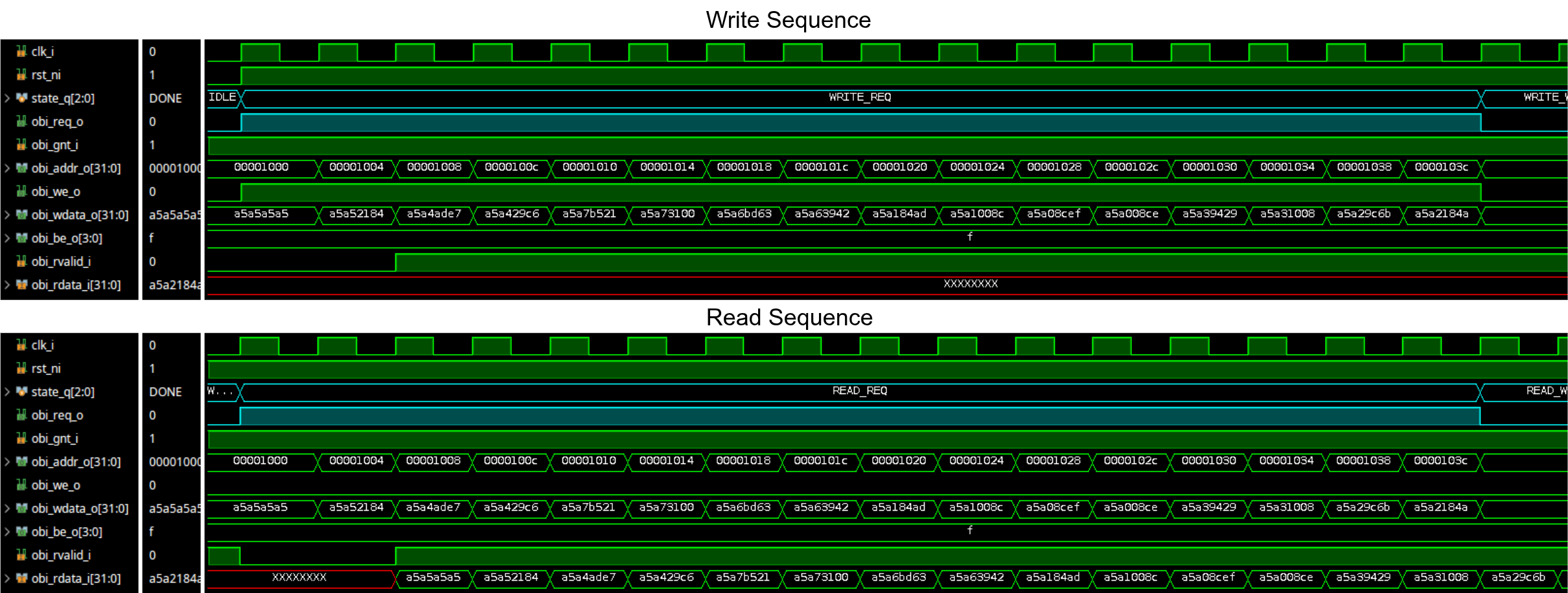
Waveform for read and write
The following waveform illustrates both read and write operations on the OBI bus. It shows how the master and slave interact during these transactions, including the handshake signals (req, gnt, rvalid) and data transfers (addr, wdata, rdata).

Part 2: Signal Dependency
Proper signal dependency rules are essential in OBI-based systems to prevent deadlocks, avoid combinatorial loops, and minimize critical timing paths, especially in large or complex designs.
-
Manager Interface Restrictions:
Thereqoutputs of a manager (master) must not be generated as a combinatorial function of thegntorrvalidinputs. For example, do not directly drivereqfromgntorrvalid. This ensures that the request logic does not create unintended feedback paths. -
Subordinate Interface Restrictions:
Thervalidoutput of a subordinate (slave) must not be a combinatorial function of thereqinput. This prevents the formation of combinatorial loops between the master and slave. -
Deadlock Prevention:
A transaction’sreqsignal must not depend on its correspondinggnt. However, it is acceptable forgntto depend onreq, as long as this does not introduce a combinatorial path that could lead to timing issues or deadlocks.
By following these dependency rules, OBI systems remain robust, free from deadlocks, and maintain predictable timing behavior.
Part 3: Designing an OBI Master
Next, we’ll design an OBI master. Instead of being controlled externally, our master will be autonomous. After reset, it will automatically perform a memory test sequence: write data to a range of addresses, read it back, and verify that the data is correct.
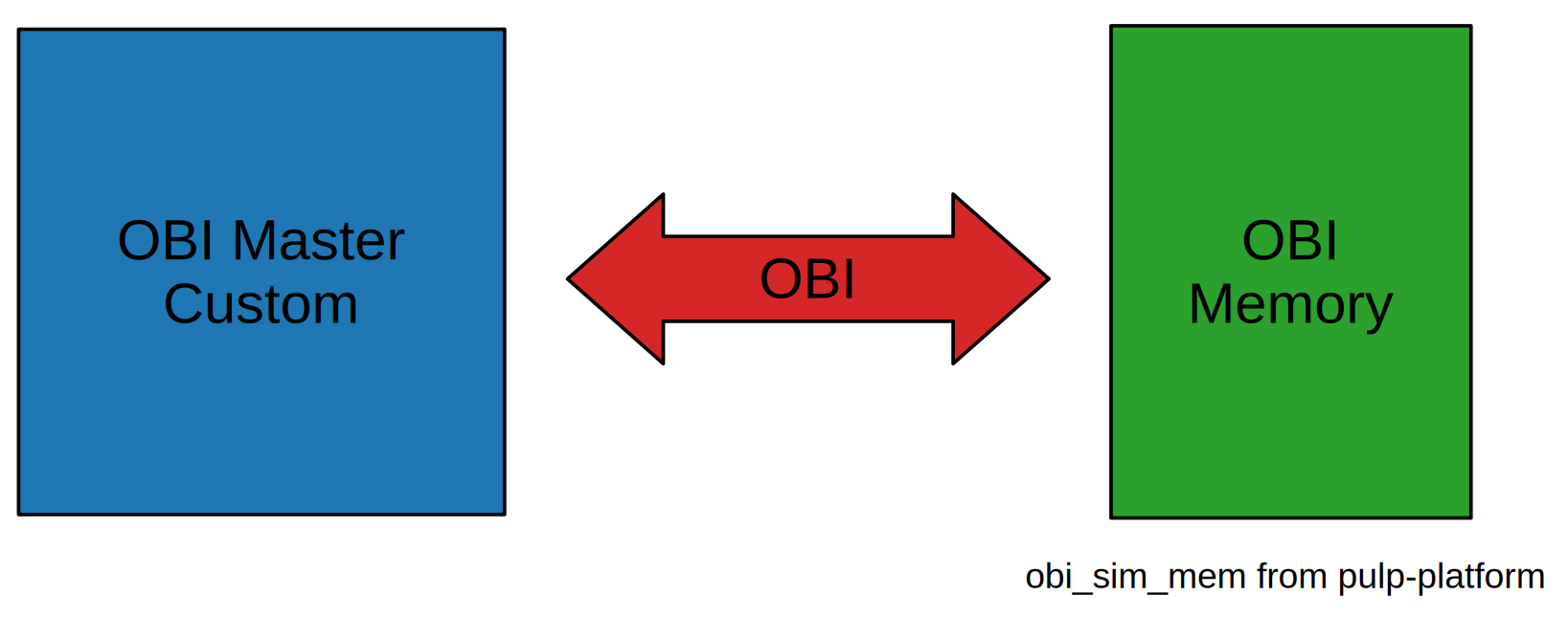
The goal is to create a master that can issue pipelined read and write requests to a slave, producing the following waveform:


Design Specification
Our master will have these features:
- Autonomous Operation: It starts a built-in self-test automatically after reset.
- Pipelined OBI Requests: It issues back-to-back requests for high throughput.
- Configurable Test Parameters: The address range and test pattern can be easily changed.
- Parallel Verification: It checks read data as it arrives from the slave.
- Status Outputs: It provides
busy,done, andpass/failsignals.
Implementation via a State Machine
The core of our autonomous master is a state machine that controls the test sequence.
typedef enum logic [2:0] {
    IDLE, WRITE_REQ, WRITE_WAIT, READ_REQ, READ_WAIT, DONE
} state_e;

state_e state_q, state_d;
Here’s a breakdown of the states:
- IDLE: Waits for reset to de-assert, then transitions to
WRITE_REQto begin the test. - WRITE_REQ: Issues a sequence of write requests. For each request, it sets the address, data, and
we=1, then assertsreq. It waits forgntbefore moving to the next address. Once all writes are issued, it moves toWRITE_WAIT. - WRITE_WAIT: A brief delay state. This ensures a clean separation on the bus between the write and read phases.
- READ_REQ: Issues read requests to the same addresses written earlier. It sets the address and
we=0, assertsreq, and waits forgnt. - READ_WAIT: Waits for all read responses to arrive. As each response comes in (
rvalidis high), it compares the receivedrdatawith the expected value and counts any errors. - DONE: The test is complete. The master holds its status outputs (
test_done_o,test_pass_o) until the next reset.
Address and Data Generation
The master needs to generate addresses and data for the test. The address is calculated by incrementing a base address. The test data is generated from a base pattern XORed with the word count, ensuring each word is unique.
// Generate address and data for the current transaction
assign current_addr   = BASE_ADDR + (word_count_q << 2); // Word-aligned
assign current_wdata  = TEST_PATTERN ^ {word_count_q, word_count_q, word_count_q, word_count_q};
WRITE_REQ State Logic
- Asserts obi_req_o, sets obi_we_o = 1.
// OBI output assignments assign obi_req_o = (state_q == WRITE_REQ) || (state_q == READ_REQ); assign obi_addr_o = current_addr; assign obi_we_o = (state_q == WRITE_REQ); assign obi_be_o = 4'hF; // Always full word accesses assign obi_wdata_o = current_wdata; - Waits for obi_gnt_i to go high, indicating the slave is ready.
- If the write is complete (all words written), it transitions to
WRITE_WAIT. If not, it increments the word count and stays inWRITE_REQto continue writing. - If the write is complete, it resets the word count and transitions to
WRITE_WAITto prepare for the read phase.// FSM Next state logic WRITE_REQ: begin if (obi_gnt_i) begin // Move to next word or switch to read phase if (word_count_q == NUM_TEST_WORDS - 1) begin word_count_d = '0; state_d = WRITE_WAIT; end else begin word_count_d = word_count_q + 1; // Stay in WRITE_REQ to continue writing end end end
Verification Logic
A simple sequential block handles the verification. When obi_rvalid_i is high during the read phase, we compare the incoming obi_rdata_i with the expected data and increment an error counter on a mismatch.
always_ff @(posedge clk_i or negedge rst_ni) begin
    // ... reset logic ...
    else if (obi_rvalid_i && (state_q == READ_REQ || state_q == READ_WAIT)) begin
        if (obi_rdata_i != expected_rdata)
            error_count_q <= error_count_q + 1;
        verify_count_q <= verify_count_q + 1;
    end
end
This master demonstrates how to drive the OBI protocol to perform a useful, autonomous task.
Simulation Waveform
Conclusion
Congratulations! You’ve walked through the design of both an OBI slave and an OBI master. You’ve learned about the core principles of the OBI protocol, how to implement its handshake and data transfer logic in SystemVerilog, and how to verify your design using a layered testing strategy.
The concepts of handshaking, pipelining, and state machine control are fundamental to digital design, and OBI provides a perfect, real-world example of their application. We encourage you to explore the provided source code, experiment with the parameters, and continue building on what you’ve learned.