SV17. FIFO Design and Implementation
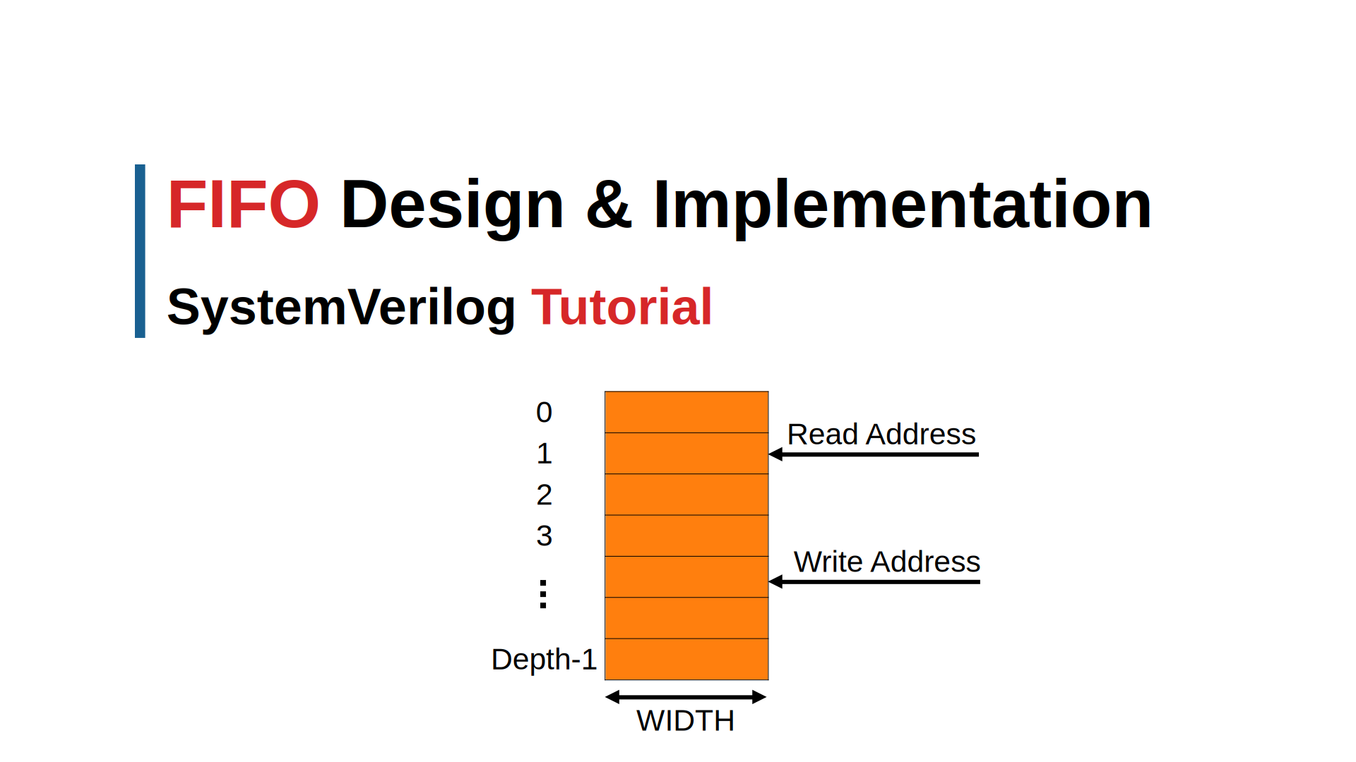
A First-In-First-Out (FIFO) buffer is a fundamental digital design component that stores data in a queue-like structure. This guide provides a comprehensive explanation of FIFO design principles, depth calculation methods, and a complete SystemVerilog implementation suitable for synthesis.
The codes are available on GitHub: aiclab-official.github.io.
Table of Contents
- Video Tutorial
- Introduction to FIFO
- Applications and Use Cases
- FIFO Depth Calculation
- Design Specification
- SystemVerilog Implementation
- Conclusion
Video Tutorial
Watch this video for a detailed explanation of FIFO design and implementation in SystemVerilog:
Introduction to FIFO
What is a FIFO?
A FIFO (First-In-First-Out) is a data structure where the first data written is the first data read. In digital design, FIFOs are implemented as circular buffers using memory arrays with read and write pointers.
Applications and Use Cases
1. Data Rate Matching
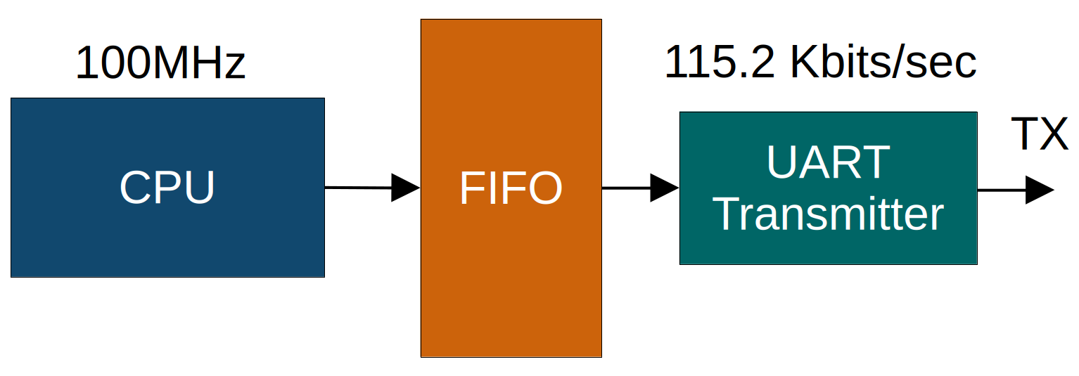
Problem Statement: Systems often have components operating at different data rates. A fast data producer can overwhelm a slower consumer, leading to data loss.
An example is shown in the figure below, where a CPU writes data at a high rate, while a slower peripheral (UART Transmitter) reads data at a lower rate. Without a buffer, the CPU could write data faster than the UART can transmit, causing data loss.
FIFO Solution:
- Acts as a buffer between mismatched data rates
- Allows burst transfers from fast producers
- Provides continuous data flow to slower consumers
- Prevents data loss during rate mismatches
2. Clock Domain Crossing
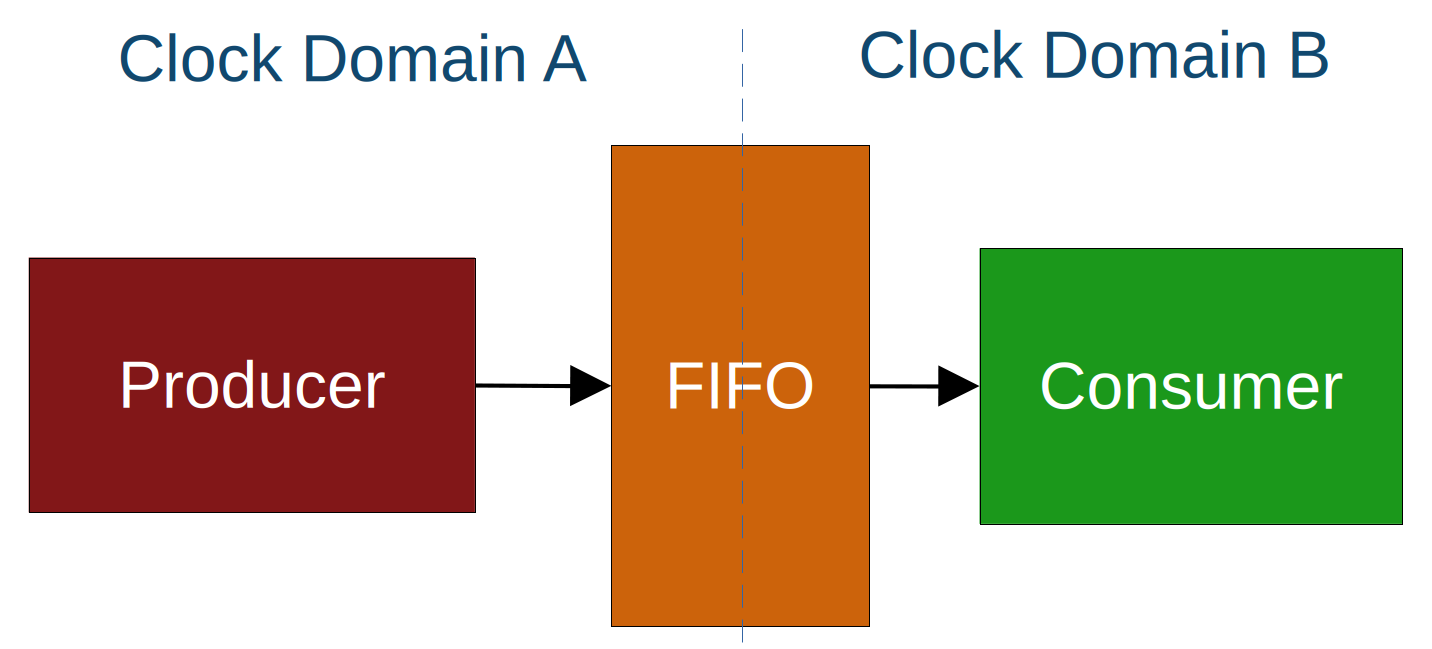
Problem Statement: Modern systems often have multiple clock domains. Transferring data between different clock frequencies can cause metastability and data corruption.
An example is shown in the figure below, where product operates in clock domain A and consumer in clock domain B. The clocks are asynchronous, meaning they do not have a fixed phase relationship. Directly transferring data between these domains can lead to metastability issues, where the data may not be stable when sampled by the receiving clock.
FIFO Solution:
- Provides safe data transfer between clock domains
- Eliminates metastability through proper synchronization
- Maintains data integrity across frequency boundaries
- Supports asynchronous read/write operations
In this guide, we will focus on the FIFO design that can be used for data rate matching, where the producer and consumer operate in the same clock domain.
3. Protocol Buffering
FIFO Applications:
- UART transmit/receive buffers
- Ethernet packet buffering
- USB data endpoints
- PCIe transaction layer buffers
FIFO Depth Calculation
Understanding the Problem
Proper FIFO depth calculation ensures no data overflow while minimizing memory usage. The calculation depends on:
- Data production rate
- Data consumption rate
- Burst characteristics
- System timing constraints
Calculation Methodology 1
Given Parameters Example
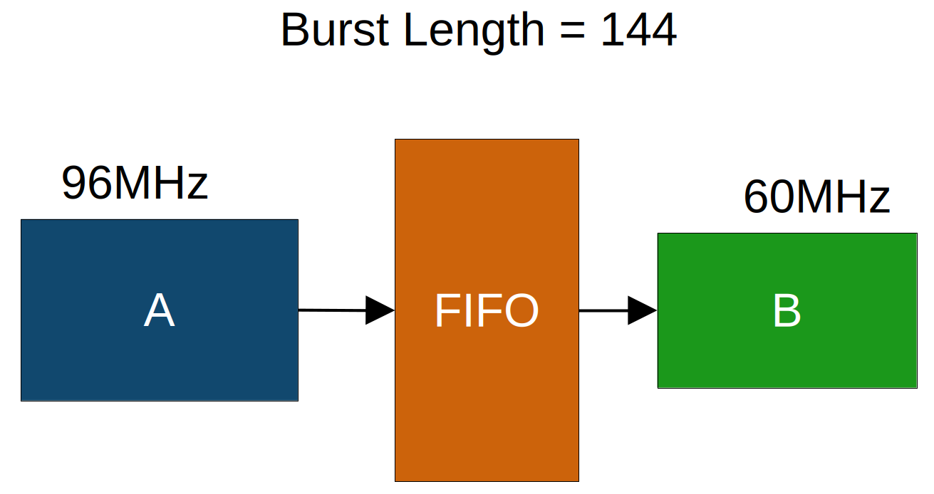
- Write clock frequency (f_A): 96 MHz
- Read clock frequency (f_B): 60 MHz
- Burst length: 144 data items
- Write idle cycles: 3 cycles between writes
- Read idle cycles: 29 cycles between reads
Step-by-Step Calculation
Step 1: Analyze Write Rate
Write idle cycles = 3
Effective write period = 4 clock cycles per data
Time to write one data = 4 × (1/96MHz) = 41.67ns
Step 2: Analyze Read Rate
Read idle cycles = 29
Effective read period = 30 clock cycles per data
Time to read one data = 30 × (1/60MHz) = 500ns
Step 3: Calculate Required Depth
Time to write entire burst = 144 × 41.67ns = 6μs
Data items read during burst = 6μs ÷ 500ns = 12 items
Required FIFO depth = 144 - 12 = 132 items
Design Specification
Functional Requirements
- Parameterizable Design
- Configurable data width (WIDTH parameter)
- Configurable depth (DEPTH parameter)
- Depth must be power of 2 for efficient addressing
- Reset Behavior
- Asynchronous active-low reset
- Reset clears all pointers and flags
- Memory contents may be undefined after reset
- Write Operations
- Synchronous to rising edge of clock
- Data written only when
wr_en_iis asserted and FIFO not full - Writes ignored when FIFO is full
- Write pointer increments after successful write
- Read Operations
- Synchronous to rising edge of clock
- Data always available on output port
- Read pointer increments only when
rd_en_iis asserted and FIFO not empty - Reads ignored when FIFO is empty
- Status Flags
full_o: Asserted when FIFO cannot accept more dataempty_o: Asserted when FIFO has no valid data- Flags updated combinationally
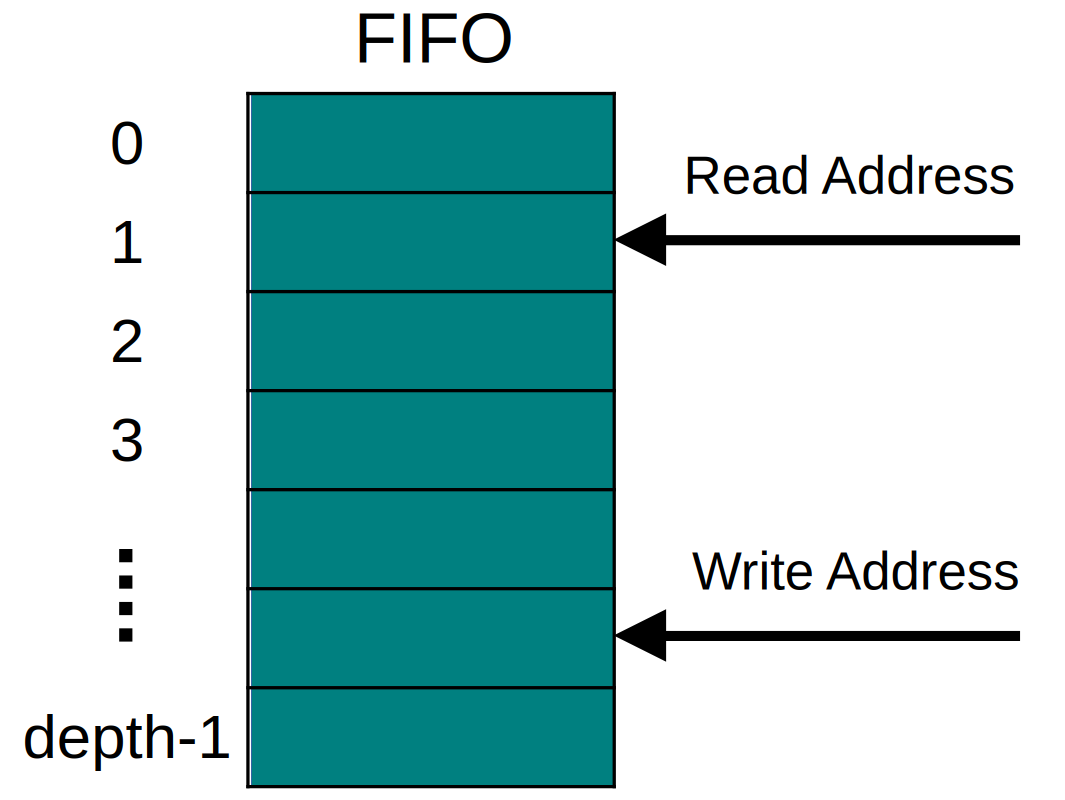
The FIFO depth must be a power of 2 to simplify pointer management. When the address reaches the maximum depth, it automatically wraps back to zero.
How to determine if the FIFO is full or empty?
When the Read Address and Write Address are equal, the FIFO can be either full or empty.
- For example, consider the Read Address pointing to address 1 and the Write Address pointing to address 9. The Reader module will read the data at addresses 1, 2, …, 9. The Read and Write Addresses are equal and both point to address 9. In this case, the FIFO is empty and the Reader module has read all the data.
- Now consider a FIFO depth of 16, with the Read Address pointing to address 1 and the Write Address pointing to address 9. The Writer module will write data at addresses 9, 10, …, 15, 0, 1. Again, the Read and Write Addresses are equal, but now the FIFO is full and the Writer module cannot write any more data.
To distinguish between full and empty states, we can use a register to track the last operation:
- If the last operation was a read, and the read and write pointers are equal, the FIFO is empty.
- If the last operation was a write, and the read and write pointers are equal, the FIFO is full.
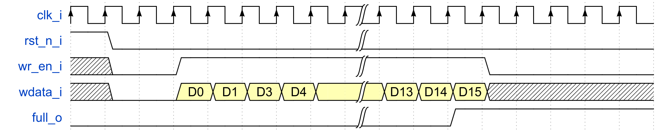
FIFO write and read operation (Depth = 16) Waveform
The FIFO write operation is illustrated in the waveform below. The Writer module puts data on the input data port and asserts the write enable signal. The FIFO accepts the data and increments the write address. When the Writer module writes the last data (D15), the FIFO asserts the full flag immediately to tell the Writer module that after this write operation, it cannot write any more data.
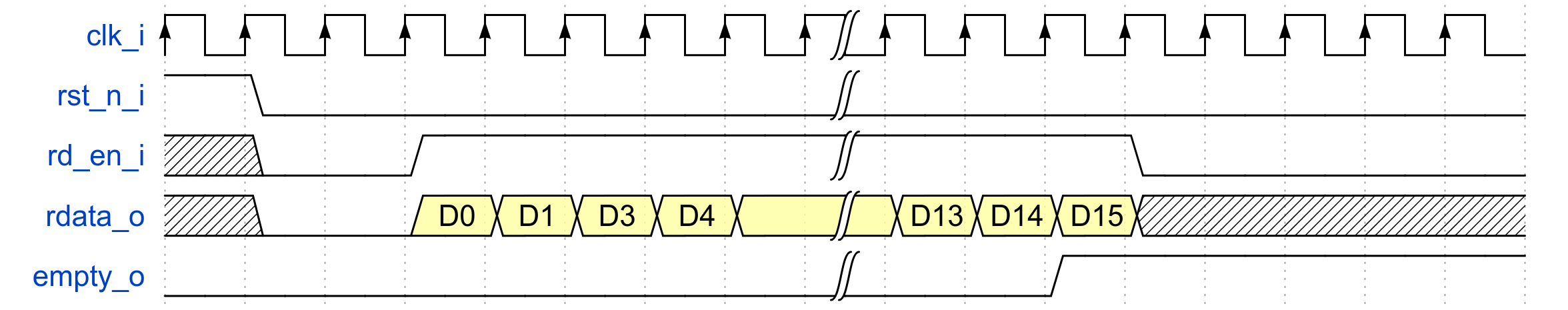
The FIFO read operation is illustrated in the waveform below. The Reader module asserts the read enable signal and reads the data from the FIFO. The FIFO provides the data on the output port and increments the read address. When the Reader module reads the last data (D15), the FIFO asserts the empty flag immediately to tell the Reader module that after this read operation, it cannot read any more data.
SystemVerilog Implementation
We will implement a synthesizable FIFO module in SystemVerilog that meets the design specifications outlined above. The implementation will include:
- Parameters
- Ports
- Time Scale
- Local Parameters
- Local Signals
- Register Array
- Function
We will implement the FIFO module step by step:
module fifo #(
    // Parameters

 )
 (
    // Ports

 );
    // Time scale

    // Local parameters

    // Local signals

    // Register Array

    // Write operation

    // Read operation

    // Last operation tracker

    // Full and Empty flags

endmodule : fifo
1. Declare parameters
Parameters allow us to configure the FIFO’s data width and depth. The depth must be a power of 2 for efficient pointer management.
module fifo #(
    // Parameters
    parameter WIDTH = 32,
    parameter DEPTH = 16
 )
 (
    // Ports

 );
    // Time scale

    // Local parameters

    // Local signals

    // Register Array

    // Write operation

    // Read operation

    // Last operation tracker

    // Full and Empty flags

endmodule : fifo
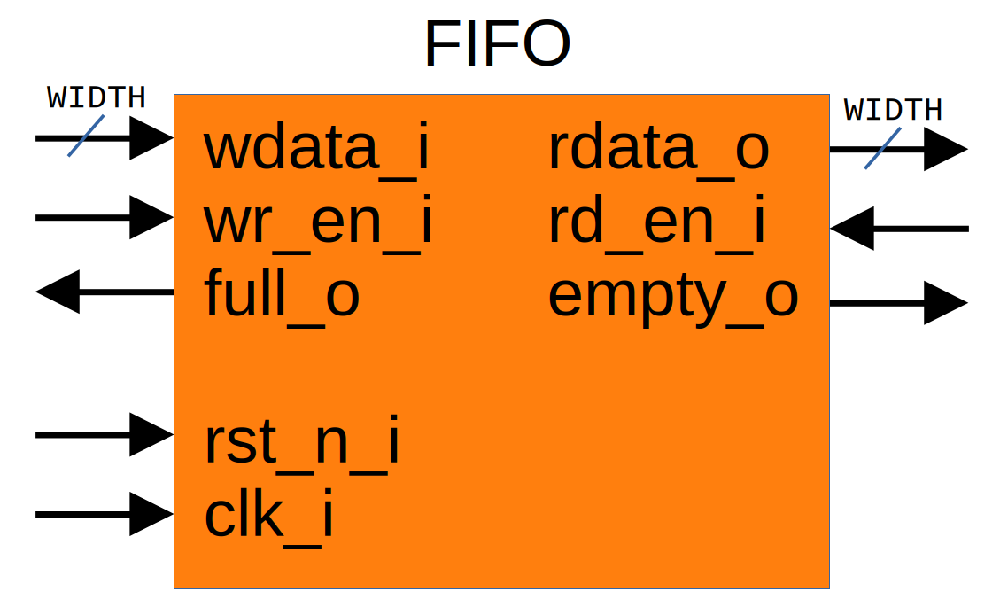
2. Declare ports
The FIFO will have input ports for clock, reset, write data, and write enable, and output ports for read data, read enable, full flag, and empty flag.
module fifo #(
    // Parameters

 )
 (
    // Ports
    //--------------------------------
    // Clock and Reset
    input  logic             clk_i,
    input  logic             rst_n_i,
    //--------------------------------
    // Write
    input  logic [WIDTH-1:0] wdata_i,
    input  logic             wr_en_i,
    output logic             full_o,
    //--------------------------------
    // Read
    output logic [WIDTH-1:0] rdata_o,
    input  logic             rd_en_i,
    output logic             empty_o
 );
    // Time scale

    // Local parameters

    // Local signals

    // Register Array

    // Write operation

    // Read operation

    // Last operation tracker

    // Full and Empty flags

endmodule : fifo
3. Signals
-
Time scale
Specifies the simulation time unit and precision for the module, ensuring consistent timing behavior. - Local parameters
$clog2returns the ceiling of the logarithm base 2 of a value.- It determines the number of address bits needed for the FIFO depth.
- Example: If
DEPTHis 8,$clog2(8)is 3, so 3 bits are needed to address 8 locations (2^3 = 8). - If
DEPTHis 10,$clog2(10)is 4, since 4 bits are required to address up to 16 locations (2^4 = 16), which covers 10.
-
Local signals
Internal signals such as read and write pointers, status flags, and operation trackers used for managing FIFO operations. - Register Array
The memory array that stores the FIFO data, typically defined as a packed array sized byWIDTHandDEPTH.
module fifo #(
    // Parameters

 )
 (
    // Ports

 );
    // Time scale
    timeunit 1ns; timeprecision 100ps;

    // Local parameters
    localparam ADDR_WIDTH = $clog2(DEPTH);

    // Local signals
    logic [ADDR_WIDTH-1:0] rptr, wptr;
    logic full, empty;
    logic last_was_read;

    // Register Array
    logic [WIDTH-1:0] mem [0:DEPTH-1];

    // Write operation

    // Read operation

    // Last operation tracker

    // Full and Empty flags

endmodule : fifo
4. Write Operation
- Check if FIFO is not full
- Store data at current write address
- Increment write pointer
- (wraps automatically with power-of-2 depth)
module fifo #(
    // Parameters

 )
 (
    // Ports

 );
    // Time scale

    // Local parameters

    // Local signals

    // Register Array

    // Write operation
    always_ff @(posedge clk_i or negedge rst_n_i) begin
        if (!rst_n_i) begin
            wptr <= 0;
        end else begin
            if (wr_en_i && !full) begin
                mem[wptr] <= wdata_i;
                wptr      <= wptr + 1'b1;
            end
        end
    end

    // Read operation

    // Last operation tracker

    // Full and Empty flags

endmodule : fifo
5. Read Operation
- Check if FIFO is not empty
- Output data from current read address
- Increment read pointer (wraps automatically)
module fifo #(
    // Parameters

)
(
    // Ports

);
    // Time scale

    // Local parameters

    // Local signals

    // Register Array

    // Write operation

    // Read operation
    always_ff @(posedge clk_i or negedge rst_n_i) begin
        if (!rst_n_i) begin
            rptr <= 0;
        end else begin
            if (rd_en_i && !empty) begin
                rptr    <= rptr + 1'b1;
                rdata_o <= mem[rptr];
            end
        end
    end
    // Last operation tracker

    // Full and Empty flags

endmodule : fifo
6. Last Operation Tracker
- Track last operation to distinguish full/empty states
- Update based on read/write enables
module fifo #(
    // Parameters

 )
 (
    // Ports

 );
    // Time scale

    // Local parameters

    // Local signals

    // Register Array

    // Write operation

    // Read operation

    // Last operation tracker
    always_ff @(posedge clk_i or negedge rst_n_i) begin
        if (!rst_n_i) begin
            last_was_read <= 1; // Initialize as empty
        end else begin
            if (rd_en_i && !empty) begin
                last_was_read <= 1;
            end else if (wr_en_i && !full) begin
                last_was_read <= 0;
            end else begin
                last_was_read <= last_was_read;
            end
        end
    end
    // Full and Empty flags

endmodule : fifo
7. Full and Empty Flags
- Pointers equal + last operation was read → FIFO is empty
- Pointers equal + last operation was write → FIFO is full
module fifo #(
    // Parameters

 )
 (
    // Ports

 );
    // Time scale

    // Local parameters

    // Local signals

    // Register Array

    // Write operation

    // Read operation

    // Last operation tracker

    // Full and Empty flags
    assign full    = (wptr == rptr) && !last_was_read;
    assign empty   = (wptr == rptr) &&  last_was_read;

    assign full_o  = full;
    assign empty_o = empty;

endmodule : fifo
This completes the FIFO module implementation.
Complete Module Implementation
module fifo #(
    parameter WIDTH = 32,
    parameter DEPTH = 16
) (
    // Clock and Reset
    input  logic             clk_i,
    input  logic             rst_n_i,
    // Write Interface
    input  logic [WIDTH-1:0] wdata_i,
    input  logic             wr_en_i,
    output logic             full_o,
    // Read Interface
    output logic [WIDTH-1:0] rdata_o,
    input  logic             rd_en_i,
    output logic             empty_o
);

    // Timing specification
    timeunit 1ns;
    timeprecision 100ps;

    // Local parameters
    localparam ADDR_WIDTH = $clog2(DEPTH);

    // Internal signals
    logic [ADDR_WIDTH-1:0] rptr, wptr;
    logic full, empty;
    logic last_was_read;

    // Memory array
    logic [WIDTH-1:0] mem [0:DEPTH-1];

    // Write operation
    always_ff @(posedge clk_i or negedge rst_n_i) begin
        if (!rst_n_i) begin
            wptr <= '0;
        end else begin
            if (wr_en_i && !full) begin
                mem[wptr] <= wdata_i;
                wptr <= wptr + 1'b1;
            end
        end
    end

    // Read operation
    always_ff @(posedge clk_i or negedge rst_n_i) begin
        if (!rst_n_i) begin
            rptr <= '0;
        end else begin
            if (rd_en_i && !empty) begin
                rptr <= rptr + 1'b1;
            end
        end
    end

    // Continuous read data assignment
    assign rdata_o = mem[rptr];

    // Last operation tracker
    always_ff @(posedge clk_i or negedge rst_n_i) begin
        if (!rst_n_i) begin
            last_was_read <= 1'b1; // Initialize as empty
        end else begin
            if (rd_en_i && !empty) begin
                last_was_read <= 1'b1;
            end else if (wr_en_i && !full) begin
                last_was_read <= 1'b0;
            end
            // else maintain current state
        end
    end

    // Status flag generation
    assign full  = (wptr == rptr) && !last_was_read;
    assign empty = (wptr == rptr) &&  last_was_read;

    assign full_o  = full;
    assign empty_o = empty;

endmodule : fifo
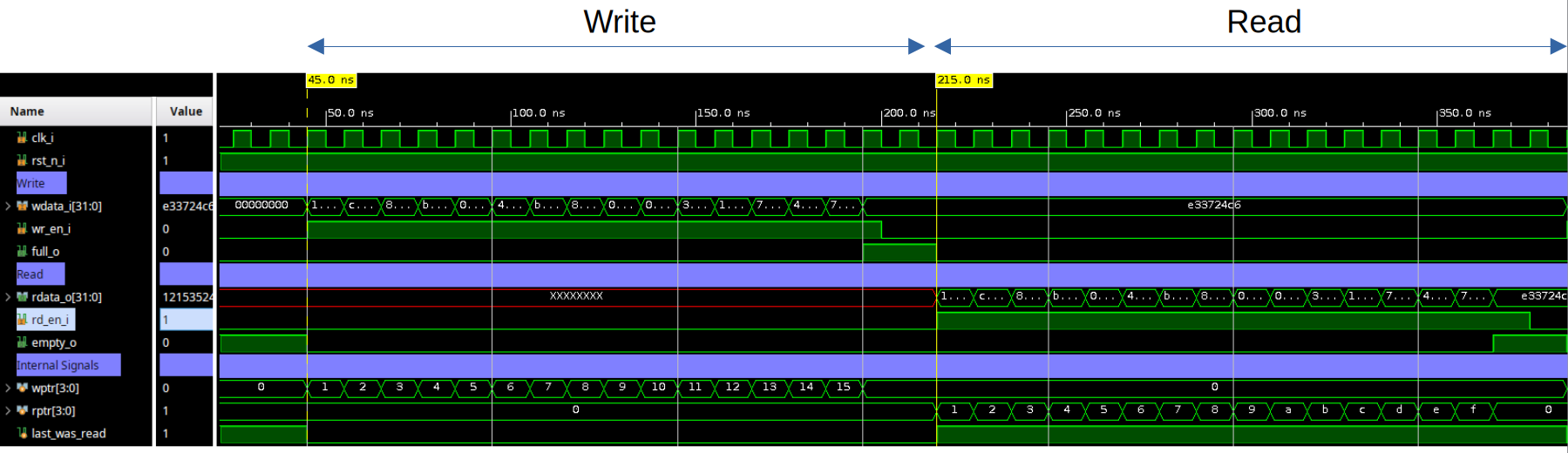
Simulation
To verify the FIFO functionality, we can create a simple testbench that simulates write and read operations, checking the status flags and data integrity.
Conclusion
This FIFO implementation provides a solid foundation for most digital design applications. The key benefits include:
- Synthesizable: Compatible with modern synthesis tools
- Parameterizable: Configurable for different applications
- Robust: Handles edge cases and error conditions
- Efficient: Optimized for both FPGA and ASIC implementations
The design follows industry best practices and can be easily integrated into larger systems. Proper verification and testing ensure reliable operation across all use cases.
References
-
P. Satish, “CALCULATION OF FIFO DEPTH - MADE EASY”, [Online]. Available: https://hardwaregeeksblog.wordpress.com/wp-content/uploads/2016/12/fifodepthcalculationmadeeasy2.pdf ↩