SV7. SystemVerilog Built-in Data types: Data Type and Types
Video Tutorial
Watch this comprehensive video explanation of Data Type and Types:
Data Type and Types in SystemVerilog
In SystemVerilog, a signal is defined with both a Data Type and a Type.
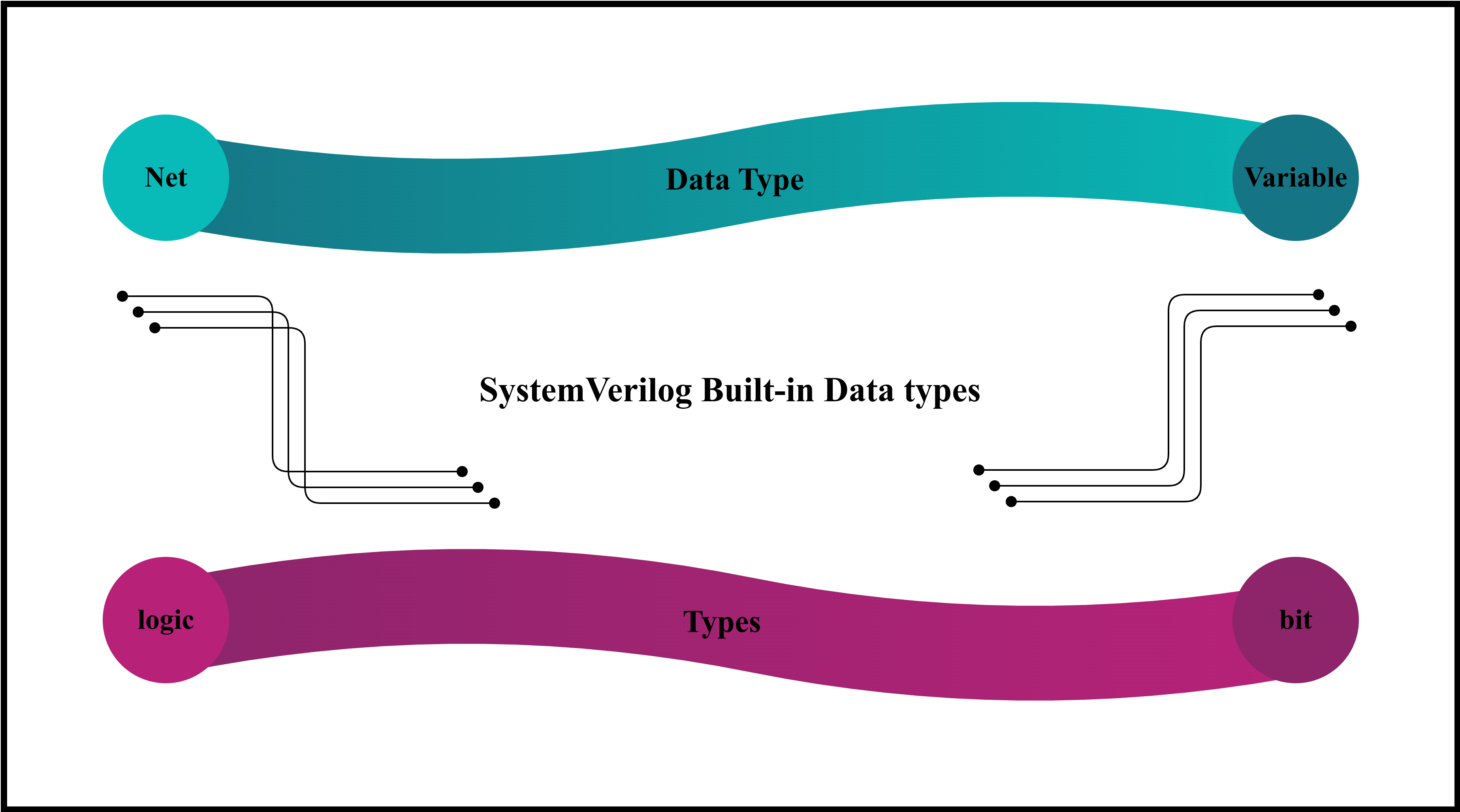
Data Type
Data types can be broadly categorized into Nets and Variables.
- Nets are like physical wires, representing connections between components. They connect a driver (source) to a receiver (destination), transmitting signals between parts of a design.
- Variables are abstract storage elements, used mainly in simulation. For synthesis, variables might translate into physical registers based on their definition and usage.
Type
Types are distinguished by the number of states they can represent:
- 2-state types: Can hold values of
0or1. -
4-state types: Can represent
0,1, high impedance (Z), or unknown (X). - The keyword
logicdeclares a variable or a net as a 4-state type. - The keyword
bitdeclares a 2-state type.
Variables can be either 2-state or 4-state types.
Nets are restricted to being only 4-state types.
Nets
Nets function as connections, not storage elements. They represent the current value of their driver, can have multiple drivers, and must be of the logic type.
If a signal is used but not explicitly declared, it is typically inferred as a net.
| Type | Description |
|---|---|
wire |
An interconnection wire that can have multiple drivers |
tri |
Exactly the same as wire. It can be used to emphasize tri-state values |
Net Data Type
Nets: Declaration and assignment examples:
Explicit continuous assignment:
wire logic [31:0] data; // 32-bit packed vector
assign data = a * b;    // Explicit continuous assignment
Implicit continuous assignment:
wire logic [31:0] data = a * b; // Implicit continuous assignment
Both methods are functionally equivalent.
Note:
- Nets cannot have subfields (e.g., no
wire logic [7:0][7:0] data8;)- Nets must be packed arrays, not unpacked arrays (e.g.,
wire logic [7:0] data8[7:0];is illegal).
Variables
Within procedural blocks (like always blocks), the left-hand side of an assignment must be a variable.
- 4-state variables: Use
var logicfor values that can be0,1,X, orZ. - 2-state variables: Use
var bitfor values restricted to0or1.
Best practice: Use the logic type for variables in RTL code to allow the simulator to detect indeterminate states (X).
Use bit type mainly for iterators in for loops or testbenches.
| Type | Description | Equivalent | n-state | Default Sign |
|---|---|---|---|---|
integer |
32-bit variable | var logic[31:0] | 4-state | signed |
bit |
General purpose variable | - | 2-state | unsigned |
byte |
8-bit variable | var bit[7:0] | 2-state | signed |
shortint |
16-bit variable | var bit[15:0] | 2-state | signed |
int |
32-bit variable | var bit[31:0] | 2-state | signed |
longint |
64-bit variable | var bit[63:0] | 2-state | signed |
Synthesizable Variable Data Types
- Use 2-state data types (
bit) primarily for validation and testbench development. This enhances simulation efficiency. - Use 4-state data types (
logic) for RTL code to catch indeterminate logic.
Logic Data Type
The logic data type is versatile:
- By default,
logicis interpreted as a variable (var logic). - For input or inout ports,
logicis interpreted as a net (wire logic).
Variables do not support multiple drivers. For multi-driven signals (e.g., tri-state buses), use
wire logicortri logic.
General guideline: Use the logic data type for signals. Use wire logic or tri logic only for multi-driven signals.
Logic (Variable): Declaration and Assignment
Scalar declaration:
logic a; // 1-bit unsigned variable
Vector declaration:
logic [31:0] data_le; // 32-bit vector, little endian (MSB is bit 31, LSB is bit 0)
logic [0:31] data_be; // 32-bit vector, big endian (MSB is bit 0, LSB is bit 31)
Signed vector:
logic signed [15:0] data_sn; // 16-bit signed variable
Bit and range select:
logic [31:0] bus;
logic [7:0] data8;
assign bus = data_le;           // copy entire data_le into bus
assign a = data_be[5];          // fixed bit select (selects bit at index 5)
assign data8 = data_le[15:8];   // 8-bit part select (bits 15 down to 8)
Important: The range in part-selects should follow the declaration’s endianness.
Variable Bit Select and Range Select
Variable bit select:
assign bus[0] = data_le[a];
Variable range select ([start +: width] or [start -: width]):
// [start +: width] expands to [start : (start + width - 1)]
// [start -: width] expands to [start : (start - width + 1)]
assign data8 = data_le[15-:8]; // equivalent to data_le[15:8]
Parameterized variable range select:
parameter WIDTH = 32;
logic [WIDTH-1:0] data;
logic [7:0] slice;
logic [4:0] start;
assign start = 3;
assign slice = data[start +: WIDTH]; // Accessing a slice based on 'start' and 'WIDTH'