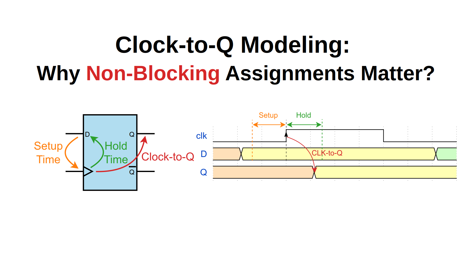
SV15. SystemVerilog Clock-to-Q Modeling: Why Non-Blocking Assignments Matter
Video Tutorial
Watch this comprehensive video explanation of Modeling Clock-to-Q Delay in SystemVerilog:
Table of Contents
- Introduction
- Understanding Flip-Flop Timing Parameters
- The RTL Simulation Challenge
- Clock-to-Q Delay in Practice
- SystemVerilog Solution: Non-Blocking Assignments
- Implementation Example
- Best Practices
- Common Pitfalls
Introduction
When designing digital circuits with flip-flops, understanding and properly modeling timing parameters is crucial for creating synthesizable and functionally correct SystemVerilog code. This guide focuses on one of the most important timing parameters: Clock-to-Q delay and how to model it effectively in RTL design.
Understanding Flip-Flop Timing Parameters
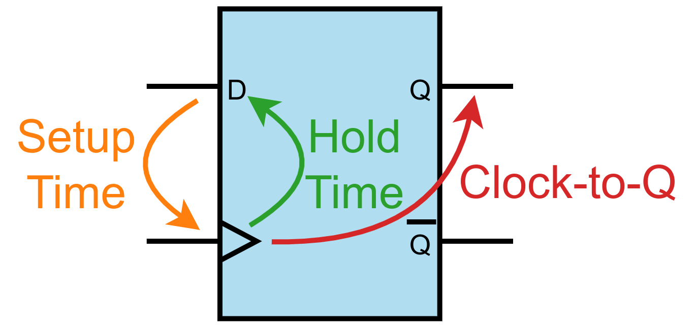
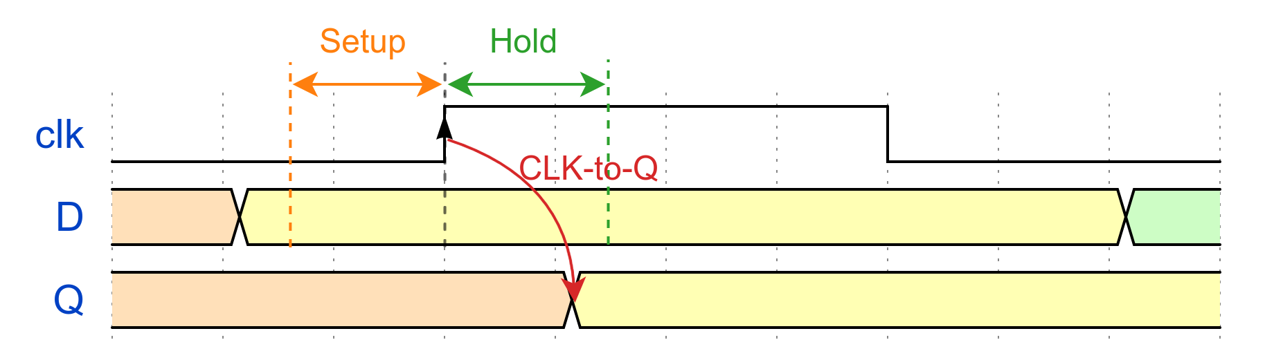
Flip-flops are fundamental building blocks of sequential digital circuits, and they have three critical timing parameters:
Setup Time
The minimum time duration that input data must be stable before the active clock edge. Violating setup time can cause metastability or incorrect data capture.
Hold Time
The minimum time duration that input data must remain stable after the active clock edge. Hold time violations can also lead to metastability.
Clock-to-Q Delay
The propagation delay from the active clock edge until the output reflects the new value.
The RTL Simulation Challenge
RTL (Register Transfer Level) modeling presents a fundamental challenge when it comes to timing:
Zero Simulation Time Abstraction
- RTL models operate in zero simulation time
- Timing parameters like setup, hold, and Clock-to-Q delays are abstracted away
- This abstraction simplifies simulation but can hide critical timing dependencies
The Instantaneous Update Problem
Without proper Clock-to-Q delay modeling:
- Flip-flop outputs change immediately after the clock edge
- Cascaded flip-flops show unrealistic instantaneous signal propagation
- Certain circuit behaviors that depend on timing delays may not be accurately represented
Real Hardware vs. RTL Simulation
In physical hardware:
- Clock-to-Q delays are finite and measurable
- Previous output values remain available during the delay period
- These delays are essential for proper operation of certain circuit topologies
Clock-to-Q Delay in Practice
Ring Counter: A Perfect Example
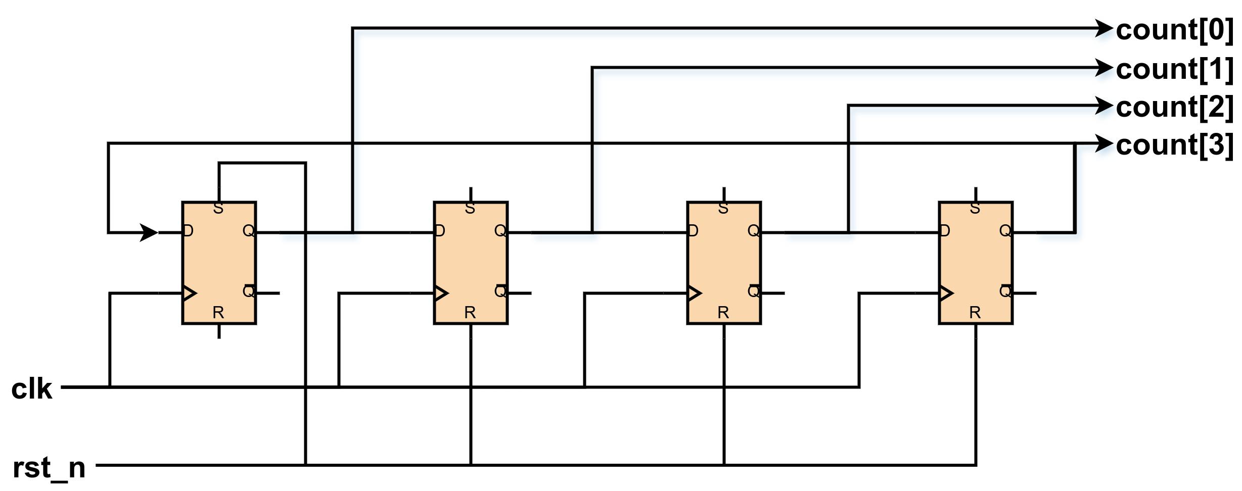
A ring counter is an excellent case study for understanding why Clock-to-Q delay modeling matters:
Circuit Function:
- Shifts a single ‘1’ bit through a sequence of flip-flops
- Creates a rotating pattern:
4'b0001→4'b0010→4'b0100→4'b1000→4'b0001
Critical Timing Dependency:
Clock Cycle N:   count = 4'b0001
                       ↓ (Clock edge occurs)
Clock Cycle N+1: count = 4'b0010
Why Clock-to-Q Delay is Essential:
- At clock edge, all flip-flops simultaneously:
- Capture their input values (based on previous outputs)
- Begin transitioning their outputs (after $T_{clk2q}$ delay)
- During $T_{clk2q}$ delay, previous output values remain stable
- This stability window allows proper data transfer between flip-flops
Without Clock-to-Q Modeling:
- All flip-flops would update simultaneously in zero time
- The circuit would lose its shifting behavior
- Simulation results would not match hardware behavior
SystemVerilog Solution: Non-Blocking Assignments
SystemVerilog provides an elegant solution through the non-blocking assignment operator (<=):
Two-Phase Execution Model
Non-blocking assignments operate in two distinct phases:
1. Evaluation Phase
- All right-hand sides of
<=assignments are evaluated - Results are stored in temporary simulation variables
- No updates to left-hand sides occur yet
2. Update Phase
- All left-hand sides are updated simultaneously from temporary values
- This phase models the Clock-to-Q delay behavior
- Creates the illusion of simultaneous updates while preserving sequential logic
How It Models Clock-to-Q Delay
// At clock edge:
count[0] <= count[3];  // RHS evaluated: current count[3] value
count[1] <= count[0];  // RHS evaluated: current count[0] value
count[2] <= count[1];  // RHS evaluated: current count[1] value
count[3] <= count[2];  // RHS evaluated: current count[2] value

// All LHS updates happen simultaneously after evaluation
This two-phase model effectively captures the essence of Clock-to-Q delay without explicit timing simulation.
Implementation Example
Here’s a complete ring counter implementation demonstrating proper Clock-to-Q delay modeling:
module ring_counter #(
    parameter WIDTH = 4
) (
    input  logic             clk,
    input  logic             rst_n,
    output logic [WIDTH-1:0] count
);

    always_ff @(posedge clk or negedge rst_n) begin
        if (!rst_n) begin
            // Initialize with single bit set
            count <= {{WIDTH-1{1'b0}}, 1'b1};
        end else begin
            // Rotate the bits using non-blocking assignments
            count[0] <= count[WIDTH-1];  // Feedback from MSB to LSB
            for (int i = 1; i < WIDTH; i++) begin
                count[i] <= count[i-1];  // Shift each bit
            end
        end
    end

endmodule
Alternative Implementation (Explicit Assignment)
always_ff @(posedge clk or negedge rst_n) begin
    if (!rst_n) begin
        count <= 4'b0001;
    end else begin
        count[0] <= count[3];  // Feedback from last to first
        count[1] <= count[0];  // Shift right
        count[2] <= count[1];  // Shift right
        count[3] <= count[2];  // Shift right
    end
end
Best Practices
1. Always Use Non-Blocking Assignments for Sequential Logic
// Correct: Non-blocking assignment
always_ff @(posedge clk) begin
    q <= d;
end

// Incorrect: Blocking assignment in sequential logic
always_ff @(posedge clk) begin
    q = d;  // Don't do this!
end
2. Separate Combinational and Sequential Logic
// Sequential logic (non-blocking)
always_ff @(posedge clk) begin
    reg_out <= reg_in;
end

// Combinational logic (blocking)
always_comb begin
    comb_out = input_a & input_b;
end
3. Use Consistent Clock Domains
// All flip-flops in same clock domain
always_ff @(posedge clk or negedge rst_n) begin
    if (!rst_n) begin
        stage1 <= '0;
        stage2 <= '0;
        stage3 <= '0;
    end else begin
        stage1 <= data_in;
        stage2 <= stage1;
        stage3 <= stage2;
    end
end
Common Pitfalls
1. Mixing Blocking and Non-Blocking Assignments
// Don't mix assignment types in sequential logic
always_ff @(posedge clk) begin
    temp = input_val;     // Blocking - executes immediately
    output_reg <= temp;   // Non-blocking - scheduled for later
end
If you need a temporary variable inside the
always_ffblock, declare it inside the block so it has block-level scope:
always_ff @(posedge clk) begin
    logic [WIDTH-1:0] temp;  // Temporary variable

    temp = input_val;        // Blocking - executes immediately
    output_reg <= temp;      // Non-blocking - scheduled for later
end
2. Race Conditions with Blocking Assignments
// Problematic: Order-dependent behavior
always_ff @(posedge clk) begin
    a = b;  // Executes immediately
    b = c;  // Executes immediately - 'a' gets old 'b' value
end

// Correct: Order-independent behavior
always_ff @(posedge clk) begin
    a <= b;  // Scheduled for update
    b <= c;  // Scheduled for update - both use current values
end
Conclusion
Proper modeling of Clock-to-Q delay through non-blocking assignments is essential for creating synthesizable SystemVerilog code that accurately represents hardware behavior. By understanding the two-phase execution model and following established best practices, designers can create robust sequential circuits that work correctly in both simulation and hardware implementation.
The ring counter example demonstrates how this seemingly simple concept has profound implications for circuit functionality, making it a cornerstone of effective RTL design methodology.