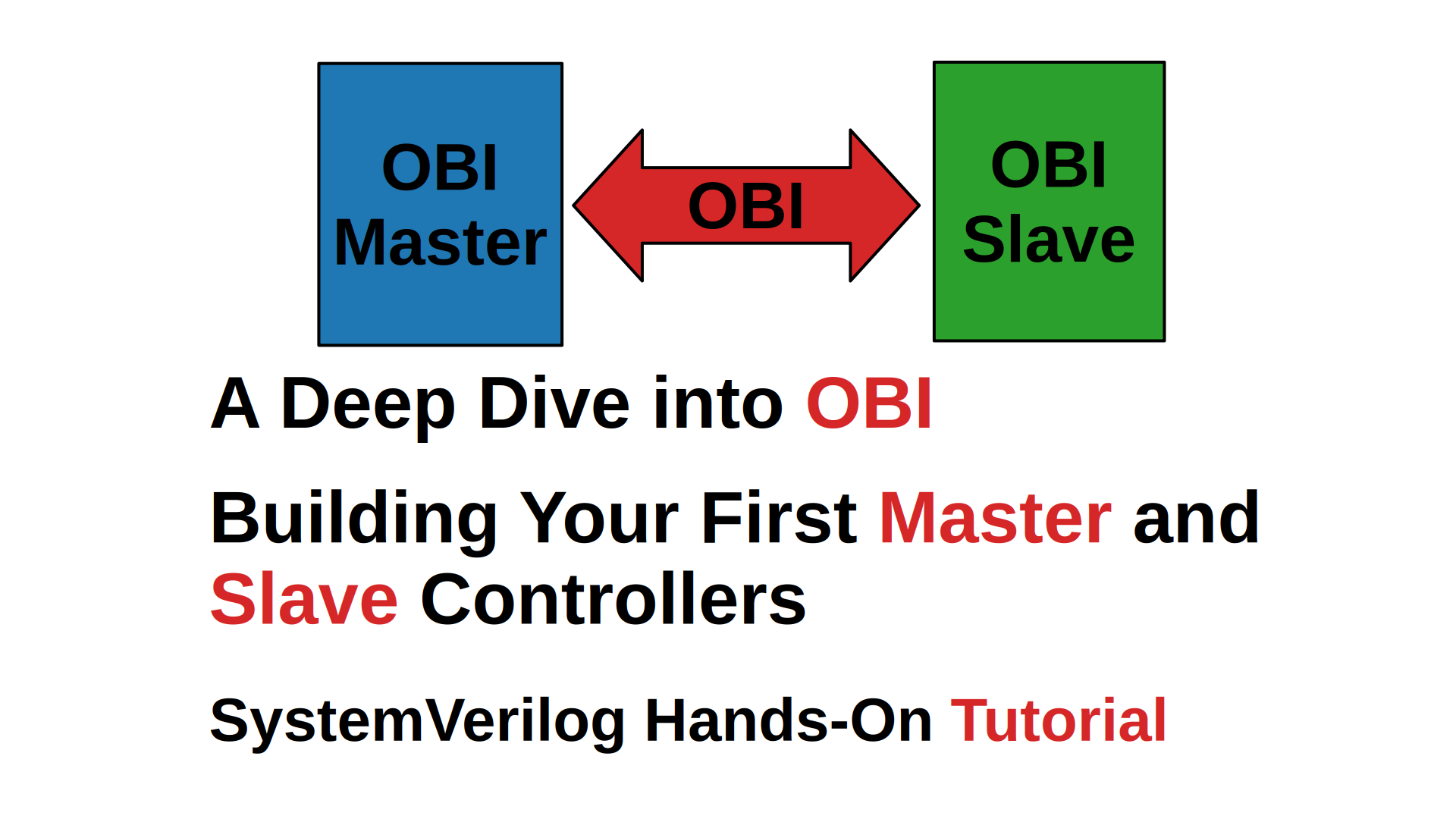
SV16. Finite State Machines (FSM)
Table of Contents
- Introduction
- Video Tutorial
- FSM Fundamentals
- State Encoding Strategies
- SystemVerilog State Definition
- FSM Coding Styles
- Default State Assignment: X-Value or State?
- FSM Style Comparison for UART Transmitter
- Best Practices for FSM Design
- Troubleshooting Common Issues
- Conclusion
- References
Introduction
Finite State Machines (FSMs) are fundamental building blocks in digital design, providing a structured approach to implementing sequential logic. This guide covers synthesizable SystemVerilog FSM design techniques, from basic concepts to advanced implementation strategies.
The codes are available on GitHub: aiclab-official.github.io.
Video Tutorial
Watch this comprehensive video explanation of FSM:
FSM Fundamentals
Basic Structure
A Finite State Machine consists of three essential components:
-
Next State Logic (Combinational)
- Determines the next state based on current state and inputs
- Implemented using combinational logic (gates, multiplexers)
- Must be free of combinational loops
-
State Register (Sequential)
- Stores the current state of the FSM
- Implemented using flip-flops or latches
- Synchronized to clock edge
-
Output Logic (Combinational or Sequential)
- Determines outputs based on current state and/or inputs
- Moore machine: outputs depend only on current state
- Mealy machine: outputs depend on current state and inputs
Moore vs Mealy Machines
Moore and Mealy machines are two common types of FSMs, differing primarily in how they generate outputs.
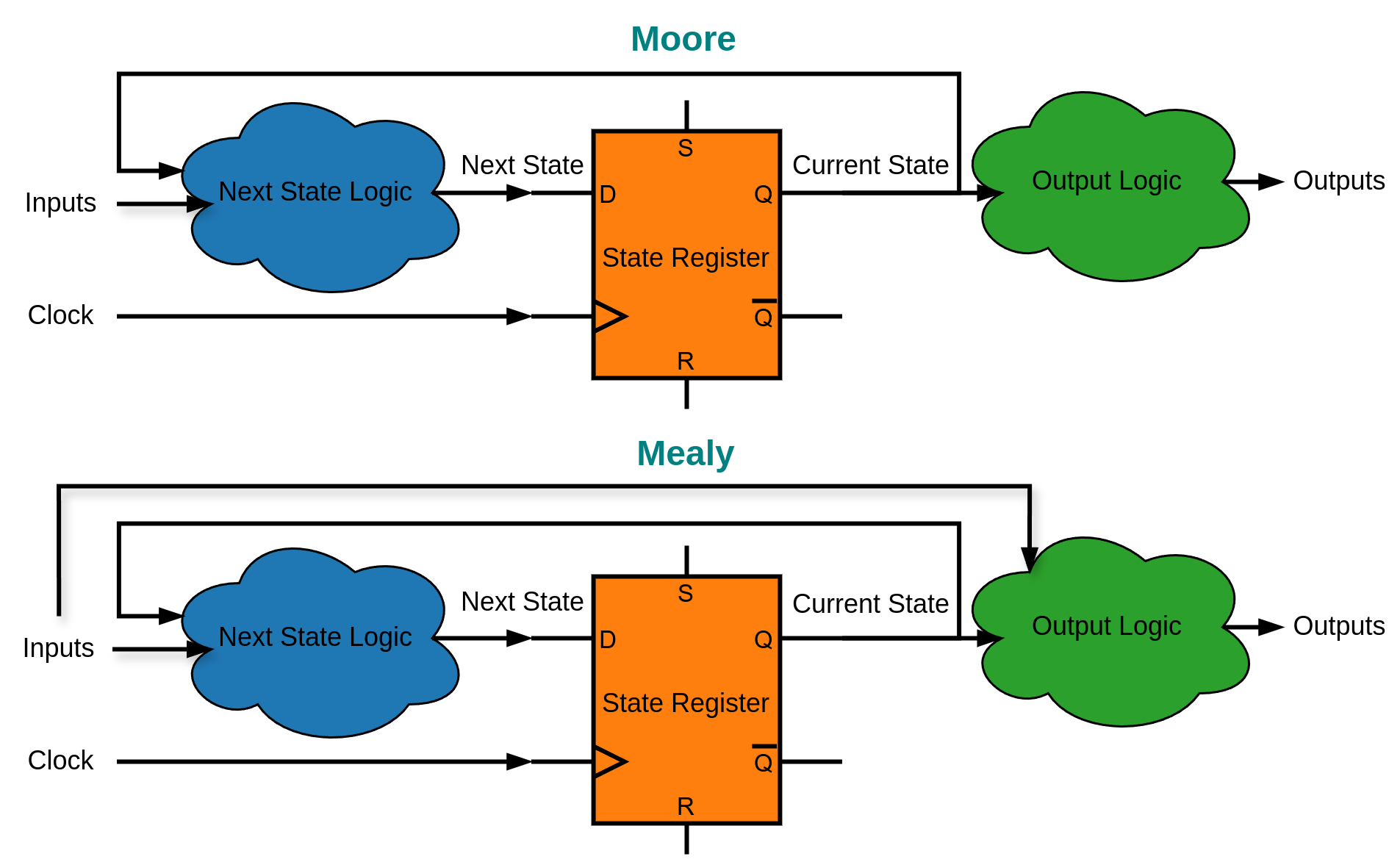
| Aspect | Moore Machine | Mealy Machine |
|---|---|---|
| Output Dependency | Current state only | Current state + inputs |
| Output Timing | Synchronized to clock | May change asynchronously |
| State Diagram | Outputs written in states | Outputs written on transitions |
| Glitch Susceptibility | Lower (synchronized) | Higher (combinational) |
| Response Time | Slower (1 clock delay) | Faster (combinational) |
| Typical Use | Control logic, protocols | Data path, fast response |
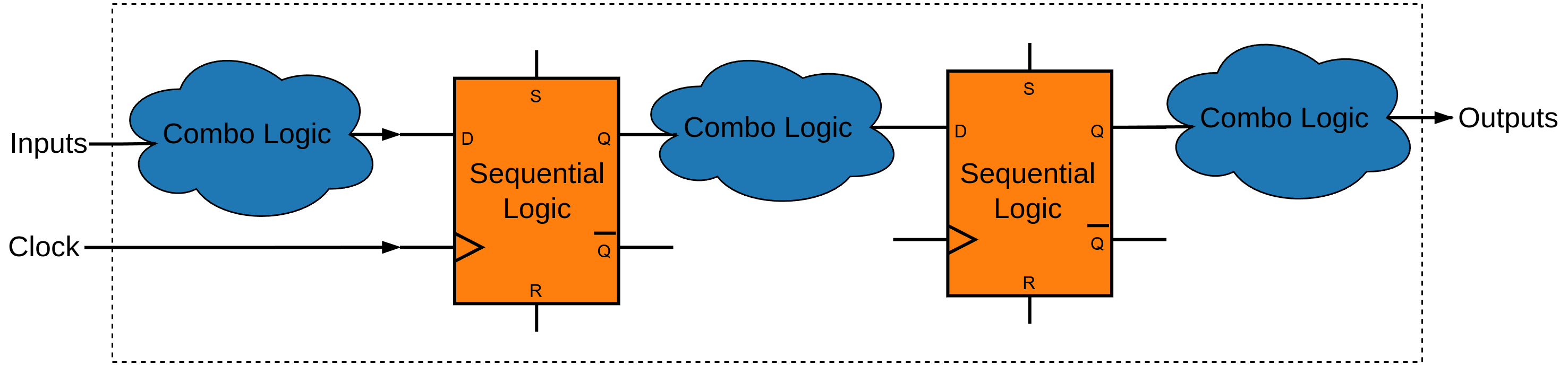
Registered Outputs and Design Partitioning
A recommended approach for partitioning a design is to use combinational logic for input processing and to have registered outputs. For internal signals between modules in an ASIC design, this approach simplifies writing timing constraints. For external signals in both FPGAs and ASICs, registered outputs produce fewer glitches because they are stable between clock edges. Therefore, in most designs, it is better to use registered outputs and to register the output of the FSM 3.
State Encoding Strategies
The choice of state encoding significantly impacts the final implementation in terms of area, timing, and power consumption.
Binary Encoding
Implementation:
typedef enum logic [1:0] {
    IDLE  = 2'b00,
    START = 2'b01,
    DATA  = 2'b10,
    STOP  = 2'b11
} state_t;
Characteristics:
- Flip-flops required: ⌈log₂(N)⌉ for N states
- Advantages:
- Minimal hardware resources
- Suitable for resource-constrained designs
- Simple state assignment
- Disadvantages:
- More complex decode logic
- Multiple bits change simultaneously (higher switching activity)
- Potential for intermediate invalid states during transitions
One-Hot Encoding (FPGA Default)
Implementation:
typedef enum logic [3:0] {
    IDLE  = 4'b0001,
    START = 4'b0010,
    DATA  = 4'b0100,
    STOP  = 4'b1000
} state_t;
Characteristics:
- Flip-flops required: N for N states
- Advantages:
- Simplest decode logic (each state is a single bit)
- Fast state transitions
- Easy to debug (state visible in single bit)
- Minimal combinational logic delay
- Natural error detection (invalid states easily identified)
- Disadvantages:
- Higher flip-flop count
- Increased power due to more flip-flops
- Larger area for high state count FSMs
Gray Code Encoding
Implementation:
typedef enum logic [1:0] {
    IDLE  = 2'b00,
    START = 2'b01,
    DATA  = 2'b11,
    STOP  = 2'b10
} state_t;
Characteristics:
- Flip-flops required: ⌈log₂(N)⌉ for N states
- Advantages:
- Only one bit changes per transition
- Reduced switching activity and power
- Minimal glitches in asynchronous circuits
- Disadvantages:
- Complex state assignment for arbitrary transition graphs
- More complex decode logic than binary
- Rarely used in synchronous designs
Johnson Counter Encoding
Implementation:
typedef enum logic [1:0] {
    IDLE  = 2'b00,
    START = 2'b01,
    DATA  = 2'b11,
    STOP  = 2'b10
} state_t;
Characteristics:
- Flip-flops required: ⌈N/2⌉ for N states
- Advantages:
- Fewer flip-flops than one-hot
- Simple generation logic
- Self-correcting properties
- Disadvantages:
- Limited to specific state sequences (Sequential Transitions without skips)
- Not suitable for arbitrary FSMs
- Complex for non-sequential state transitions
Encoding Selection Guidelines
| Design Priority | Recommended Encoding | Why? |
|---|---|---|
| Minimum Area | Binary | Fewest flip-flops |
| Maximum Speed | One-Hot | Minimal decode logic |
| Low Power | Gray | Minimal switching |
| General Purpose | Let synthesis tool decide | Optimal for specific constraints |
Note:
- In ASICs, flip-flops are often more expensive than combinational logic. A flip-flop requires approximately 25 transistors, while a 2-input gate requires about 4 transistors. Additionally, each flip-flop needs a clock signal, which consumes power on every clock edge. The best encoding strategy depends on the specific design constraints and goals.
- In FPGAs, combinational logic is typically more expensive than flip-flops. FPGAs have a large number of flip-flops available—more than enough for most designs. FPGA performance is often limited by routing delay and the number of look-up tables (LUTs) needed to implement the combinational logic. Therefore, one-hot encoding is often preferred in FPGAs for its simplicity and speed. In Vivado, if
FSM_ENCODINGis set toauto, the tool ignores the encoding you use in RTL code; for up to 32 states, it will be encoded as one-hot 1, 2.
SystemVerilog State Definition
Enumerated Data Types
SystemVerilog provides powerful enumerated types for FSM state definition:
// Basic enumeration
typedef enum {IDLE, START, DATA, STOP} state_t;

// Explicit encoding with bit width
typedef enum logic [3:0] {
    IDLE  = 4'b0001,
    START = 4'b0010,
    DATA  = 4'b0100,
    STOP  = 4'b1000
} state_t;

// Automatic assignment
typedef enum logic [2:0] {
    IDLE  = 3'b000,
    START,
    DATA,
    STOP,
} state_t;
Benefits of Enumerated Types
- Type Safety: Prevents assignment of invalid values
- Readability: Self-documenting code with meaningful names
- Maintainability: Easy to add/remove states
- Tool Support: Better synthesis optimization and debugging
- Simulation: Clear state names in waveforms
FSM Coding Styles
Three-Block Coding Style
The three-block coding style separates the FSM into distinct functional blocks, providing maximum clarity and maintainability.
Block 1: Next State Logic
// Combinational logic block
always_comb begin
    // Default assignment prevents latches
    next_state = current_state;

    case (current_state)
        IDLE:  if (tx_start)                       next_state = START;
        START: if (baud_tick)                      next_state = DATA;
        DATA:  if (baud_tick && bit_count == DW-1) next_state = STOP;
        STOP:  if (baud_tick)                      next_state = IDLE;
        default:                                   next_state = IDLE;
    endcase
end
Key Points:
- Use
always_combfor synthesizable combinational logic - Always include default assignment to prevent latches
- Include
defaultcase for robustness - Structure with clear state-by-state logic
Block 2: State Register
// Sequential logic block for state storage
always_ff @(posedge clk or negedge rst_n) begin
    if (!rst_n) current_state <= IDLE;  // Asynchronous reset to known state
    else        current_state <= next_state;
end
Key Points:
- Use
always_fffor sequential logic - Include asynchronous reset for reliable startup
- Reset to a known, safe state (typically IDLE)
- Consider synchronous reset for some applications
Block 3: Output Logic
// Combinational output logic (Moore machine)
always_comb begin
    // Default outputs
    tx = 1'b1;
    tx_busy = 1'b0;

    case (current_state)
        IDLE: begin
                tx = 1'b1;
                tx_busy = 1'b0;
              end
        START: begin
                tx = 1'b0;
                tx_busy = 1'b1;
               end
        DATA: begin
                tx = tx_shift_reg[0];
                tx_busy = 1'b1;
              end
        STOP: begin
                tx = 1'b1;
                tx_busy = 1'b1;
              end
        default: begin
                tx = 1'b1;
                tx_busy = 1'b0;
              end
    endcase
end

// Alternative: Simple assignments for some outputs
assign tx_busy = (current_state != IDLE);
Advantages of Three-Block Style
- Clear Separation of Concerns
- Excellent Maintainability
- Predictable Synthesis Results
Two-Block Coding Styles
Style 1: Combined Next State and Output Logic
// State register
always_ff @(posedge clk or negedge rst_n) begin
    if (!rst_n) current_state <= IDLE;
    else        current_state <= next_state;
end

// Combined next state and output logic
always_comb begin
    // Default assignments
    next_state = current_state;
    tx = 1'b1;
    tx_busy = 1'b0;

    case (current_state)
        IDLE: begin
            tx = 1'b1;
            tx_busy = 1'b0;
            if (tx_start)  next_state = START;
        end
        START: begin
            tx = 1'b0;
            tx_busy = 1'b1;
            if (baud_tick) next_state = DATA;
        end
        DATA: begin
            tx = tx_shift_reg[0];
            tx_busy = 1'b1;
            if (baud_tick && bit_count == DW-1) next_state = STOP;
        end
        STOP: begin
            tx = 1'b1;
            tx_busy = 1'b1;
            if (baud_tick) next_state = IDLE;
        end
        default: begin
            next_state = IDLE;
            tx = 1'b1;
            tx_busy = 1'b0;
        end
    endcase
end
When to Use:
- Complex shared logic between next state and output decisions
- When output logic directly influences state transitions
- Compact representation needed
Trade-offs:
- Reduced code duplication vs. decreased modularity
- Faster development vs. harder maintenance
Style 2: Sequential Outputs
// Next state logic
always_comb begin
    next_state = current_state;

    case (current_state)
        IDLE:    if (tx_start)  next_state = START;
        START:   if (baud_tick) next_state = DATA;
        DATA:    if (baud_tick && bit_count == DW-1) next_state = STOP;
        STOP:    if (baud_tick) next_state = IDLE;
        default:                next_state = IDLE;
    endcase
end

// State register and output logic combined
always_ff @(posedge clk or negedge rst_n) begin
    if (!rst_n) begin
        current_state <= IDLE;
        tx <= 1'b1;
        tx_busy <= 1'b0;
    end
    else begin
        current_state <= next_state;

        // Outputs updated synchronously with state
        case (next_state)  // Note: using next_state
            IDLE: begin
                tx <= 1'b1;
                tx_busy <= 1'b0;
            end
            START: begin
                tx <= 1'b0;
                tx_busy <= 1'b1;
            end
            DATA: begin
                tx <= tx_shift_reg[0];
                tx_busy <= 1'b1;
            end
            STOP: begin
                tx <= 1'b1;
                tx_busy <= 1'b1;
            end
            default: begin
                tx <= 1'b1;
                tx_busy <= 1'b0;
            end
        endcase
    end
end
Advantages:
- Outputs change synchronously with state transitions
- No combinational output delays
- Glitch-free outputs
Considerations:
- Outputs delayed by one clock cycle
- May require additional state for immediate response
- More complex reset logic
One-Block Coding Style
This style combines all FSM logic into a single block.
always_ff @(posedge clk or negedge rst_n) begin
    if (!rst_n) begin
        current_state <= IDLE;
        tx      <= 1'b1;
        tx_busy <= 1'b0;
    end
    else begin
        case (current_state)
            IDLE: begin
                tx      <= 1'b1;
                tx_busy <= 1'b0;
                if (tx_start)   current_state <= START;
            end
            START: begin
                tx      <= 1'b0;
                tx_busy <= 1'b1;
                if (baud_tick)  current_state <= DATA;
            end
            DATA: begin
                tx      <= tx_shift_reg[0];
                tx_busy <= 1'b1;
                if (baud_tick && bit_count == DW-1) current_state <= STOP;
            end
            STOP: begin
                tx <= 1'b1;
                tx_busy <= 1'b1;
                if (baud_tick)  current_state <= IDLE;
            end
            default: begin
                current_state <= IDLE;
                tx      <= 1'b1;
                tx_busy <= 1'b0;
            end
        endcase
    end
end
Advantages:
- Simplified design with fewer blocks
- Easier to read for small FSMs
- Reduced code duplication
- Less overhead for small FSMs
Disadvantages:
- Harder to maintain for complex FSMs
- Less modularity
- Outputs may glitch if not carefully managed
- Less clear separation of concerns
Best FSM Coding Styles
The choice between three-block, two-block, or one-block FSM coding styles depends on the complexity of the FSM, design requirements, and personal preference. There is no universally “best” style; each approach offers distinct advantages and trade-offs. Modern synthesis tools are generally capable of optimizing FSMs regardless of the coding style used, so you should select the style that best fits your project’s needs and your own workflow.
Default state assignment: X-Value or State
In SystemVerilog, the default state assignment can be either an X-value or a specific state.
Here are the reasons why the X-value assignment style is recommended 2:
- Debugging Advantage: X-values can help identify missing states during simulation, in waveforms the X-values will be highlighted red, making it easier to catch errors. In contrast, specific state assignments may work correctly for some clock cycles but fail later, leading to harder-to-diagnose issues.
- Synthesis Advantage: In synthesis, X-values is treated as a don’t-care (X) condition, allowing the synthesis tool to optimize the logic more effectively. This can lead to smaller and more efficient hardware implementations.
Here are the reasons why the X-value assignment style is not recommended 6:
- Outdated Practice: While assigning ‘x’ for “don’t care” conditions was a common practice in legacy Verilog for logic optimization, it is now considered obsolete. SystemVerilog introduced unique and priority modifiers, which provide the same gate-level reduction while adding the significant advantage of built-in runtime simulation checks.
- Reduced Robustness: Using ‘x’ assignments for logic optimization results in a less robust design because it removes hardware for conditions assumed to be impossible. If a glitch forces the circuit into one of these unhandled states, the behavior becomes unpredictable. In contrast, a fully specified design is more resilient to unexpected events like power-on glitches or interference because it defines a predictable outcome for every possible condition.
I subscribe to the second argument and prefer specifying a default state over using X-value assignments. In today’s submicron technologies, optimizing a couple of transistors has little to no effect on area or power consumption, and it is not worth the cost of reducing the design’s robustness.
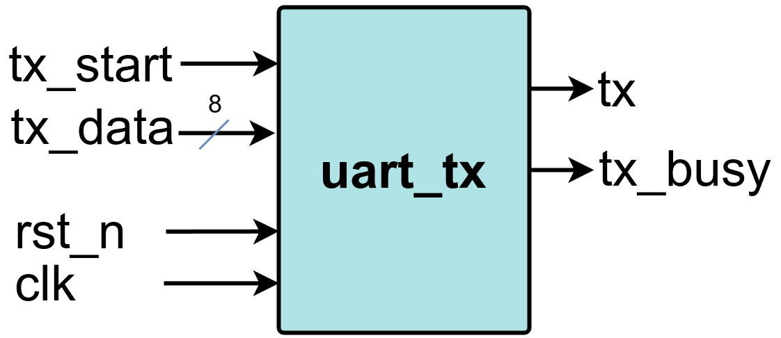
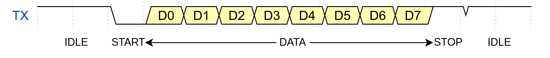
FSM Style Comparison for UART Transmitter
This example provides a comparison of different FSM (Finite State Machine) coding styles in SystemVerilog, using a UART transmitter as the example design. It is intended to be used with Xilinx Vivado. All implementations target the same UART transmitter functionality and use identical constraints. All implementations pass the same gate-level simulation tests, ensuring functional equivalence.
| FSM Style | WNS (ns) | TNS (ns) | WHS (ns) | THS (ns) | WBRS | TPWS | Total Power (W) | Failed Routes | Methodology Violations | LUT | FF |
|---|---|---|---|---|---|---|---|---|---|---|---|
| One Block | 6.138 | 0 | - | 0.167 | 0 | 0 | 0.147 | 0 | 10 Warn | 29 | 26 |
| Two Block Combinational | 6.176 | 0 | - | 0.197 | 0 | 0 | 0.147 | 0 | 10 Warn | 29 | 25 |
| Two Block Sequential | 6.138 | 0 | - | 0.167 | 0 | 0 | 0.147 | 0 | 10 Warn | 29 | 26 |
| Three Block | 6.176 | 0 | - | 0.197 | 0 | 0 | 0.147 | 0 | 10 Warn | 29 | 25 |
Timing Performance
- Worst Negative Slack (WNS): All implementations achieve positive slack, indicating timing requirements are met
- Two Block Combinational and Three Block styles show slightly better WNS (6.176 ns vs 6.138 ns)
- All designs have zero Total Negative Slack (TNS), confirming no timing violations
Resource Utilization
- LUT Usage: Consistent across all styles (29 LUTs)
- Flip-Flop Usage:
- Two Block Combinational and Three Block: 25 FFs
- One Block and Two Block Sequential: 26 FFs
- The two-block combinational and three-block styles show 1 FF savings, because they do not register the output of the combinational logic.
Recommendations
The implementation results demonstrate that FSM coding style choice should prioritize code readability, maintainability, and team preferences rather than performance concerns for this particular design complexity.
Best Practices for FSM Design
Code Organization
-
Use Meaningful Names
// Good typedef enum logic [2:0] { WAIT_FOR_START, RECEIVE_DATA_BITS, CHECK_PARITY, PROCESS_STOP_BIT } uart_rx_state_t; // Avoid typedef enum logic [2:0] { S0, S1, S2, S3 } state_t; -
Include Comprehensive Comments
-
Consistent Coding Style
// Use consistent indentation and formatting
always_comb begin
    case (current_state)
        STATE_A: begin
            if (condition_1)
                next_state = STATE_B;
            else if (condition_2)
                next_state = STATE_C;
        end
        STATE_B: begin
            if (condition_3)
                next_state = STATE_A;
        end
    endcase
end
Reset Strategy
-
Asynchronous Reset for Reliability (ASIC Designs)
always_ff @(posedge clk or negedge rst_n) begin if (!rst_n) begin current_state <= IDLE; // Reset all registers to known values counter <= '0; data_reg <= '0; end else begin current_state <= next_state; // Normal operation end end -
Synchronous Reset for Timing (FPGA Designs)
always_ff @(posedge clk) begin
    if (!rst_n) begin
        current_state <= IDLE;
    end
    else begin
        current_state <= next_state;
    end
end
Error Handling
-
Always Include Default Cases
always_comb begin next_state = current_state; case (current_state) IDLE: /* state logic */; START: /* state logic */; DATA: /* state logic */; STOP: /* state logic */; // Handle unexpected states default: begin next_state = IDLE; // Safe recovery state // Optional: Assert error signal // error_flag = 1'b1; end endcase end -
State Validation
// Optional: Add state validation for debugging
always_ff @(posedge clk) begin
    case (current_state)
        IDLE, START, DATA, STOP: begin
            // Valid states - no action needed
        end
        default: begin
            $error("Invalid FSM state detected: %b", current_state);
            // Could also assert a signal for hardware detection
        end
    endcase
end
Performance Optimization
-
Minimize Critical Path
// Good: Simple next state logic always_comb begin case (current_state) IDLE: next_state = start ? STATE_1 : IDLE; STATE_1: next_state = done ? IDLE : STATE_2; STATE_2: next_state = error ? IDLE : STATE_1; endcase end // Avoid: Complex expressions in state logic always_comb begin case (current_state) IDLE: begin if (start && !busy && data_valid && (counter < MAX_COUNT)) next_state = STATE_1; // Long critical path end endcase end -
Pipeline Complex Conditions
// Pre-compute complex conditions
logic transition_condition;

always_ff @(posedge clk) begin
    transition_condition <= start && !busy && data_valid && (counter < MAX_COUNT);
end

always_comb begin
    case (current_state)
        IDLE: next_state = transition_condition ? STATE_1 : IDLE;
    endcase
end
Hierarchical FSMs
For complex control logic, consider hierarchical FSM structures:
// Top-level FSM
typedef enum logic [1:0] {
    INIT,
    PROCESSING,
    ERROR_HANDLING,
    SHUTDOWN
} main_state_t;

// Sub-FSM for processing state
typedef enum logic [2:0] {
    PROC_IDLE,
    PROC_SETUP,
    PROC_EXECUTE,
    PROC_CLEANUP,
    PROC_DONE
} proc_state_t;

main_state_t main_current, main_next;
proc_state_t proc_current, proc_next;

// Main FSM
always_comb begin
    main_next = main_current;

    case (main_current)
        INIT:
            if (init_complete) main_next = PROCESSING;
        PROCESSING:
            if (proc_error) main_next = ERROR_HANDLING;
            else if (proc_complete) main_next = SHUTDOWN;
        ERROR_HANDLING:
            if (error_cleared) main_next = PROCESSING;
        SHUTDOWN:
            if (shutdown_complete) main_next = INIT;
    endcase
end

// Processing sub-FSM (active only when main FSM is in PROCESSING)
always_comb begin
    proc_next = proc_current;

    if (main_current == PROCESSING) begin
        case (proc_current)
            PROC_IDLE:   if (start_proc) proc_next = PROC_SETUP;
            PROC_SETUP:  if (setup_done) proc_next = PROC_EXECUTE;
            PROC_EXECUTE:if (exec_done) proc_next = PROC_CLEANUP;
            PROC_CLEANUP:if (cleanup_done) proc_next = PROC_DONE;
            PROC_DONE:   proc_next = PROC_IDLE;
        endcase
    end
    else begin
        proc_next = PROC_IDLE;  // Reset sub-FSM when not active
    end
end
Troubleshooting Common Issues
Common Issues and Solutions
1. Inferred Latches
Problem:
// WRONG: Missing default case creates latch
always_comb begin
    case (current_state)
        IDLE:  output_signal = 1'b0;
        START: output_signal = 1'b1;
        // Missing DATA and STOP cases!
    endcase
end
Solution:
// CORRECT: Complete case coverage
always_comb begin
    // Default assignment
    output_signal = 1'b0;

    case (current_state)
        IDLE:    output_signal = 1'b0;
        START:   output_signal = 1'b1;
        DATA:    output_signal = data_bit;
        STOP:    output_signal = 1'b1;
        default: output_signal = 1'b0;
    endcase
end
2. Race Conditions
Problem:
// WRONG: Using next_state in output logic can create races
always_comb begin
    case (next_state)  // Dangerous!
        IDLE:  output = 1'b0;
        START: output = 1'b1;
    endcase
end
Solution:
// CORRECT: Use current_state for Moore machine outputs
always_comb begin
    case (current_state)
        IDLE:  output = 1'b0;
        START: output = 1'b1;
    endcase
end
Conclusion
Mastering Finite State Machines is a cornerstone of expert digital design. This guide has walked you through the critical decisions you’ll face, from choosing between Moore and Mealy architectures to selecting the right encoding and coding style for your specific goals. We’ve seen that while styles like one-hot encoding or a three-block structure have distinct advantages, modern synthesis tools are highly effective at optimization. This shifts the priority to readability, maintainability, and robustness.
Ultimately, the “best” FSM is one that is easy to understand, debug, and scale. By leveraging SystemVerilog’s enumerated types, applying consistent best practices, and always designing for unexpected conditions, you will create high-quality, synthesizable logic that stands the test of time. Apply these principles to your next project to build more efficient and reliable digital systems.